| META TOPICPARENT |
name="MinimalLectures" |
Analogue Signals
Up to now, we only treated digital signals in output mode (LED) and in input mode (pushbutton). Sensors often produce analogue signal levels, however. A thermistor, for example, returns a voltage level which corresponds to the temperature. How can we treat signals like these?
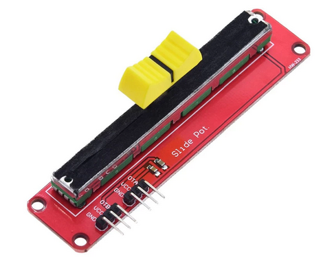
Our slider potentiometer produces a similar signal level, and we will connect it to an Analogue to Digital Converter (ADC). The ESP32 chip already supplies a 12 bit ADC. With 12 bits 4096 different numbers can be represented, and we therefore get a resolution of our measurement of 1/4096 which corresponds to ~0.025 %
 The potentiometer has 3 pins: OTA (or OTB), VCC, GND which must be connected to the triple base as follows:
Use the male/female Dupont wires to make the connections.
You find a description of the MicroPython driver in the doc
 again. The ADC works for a range of 0..1V only while the potentiometer produces signal levels of 0..3.3V. A signal attenuator allows adapting the ranges. It must be set to ADC.ATTN_11DB for our 0..3.3V slider. again. The ADC works for a range of 0..1V only while the potentiometer produces signal levels of 0..3.3V. A signal attenuator allows adapting the ranges. It must be set to ADC.ATTN_11DB for our 0..3.3V slider.
from machine import ADC,Pin
from time import sleep_ms
slider = ADC(Pin(36, atten=ADC.ATTN_11DB) # use the ADC on GPIO 36 and set the attenuator to 11 dB
while True:
print("Raw 12 bit value from slider: ",slider.read())
sleep_ms(100)
The only hardware still missing is the rgb LED chain
--  Uli Raich - 2022-10-16 Uli Raich - 2022-10-16
Comments
| META FILEATTACHMENT |
attachment="slider.png" attr="" comment="" date="1665953663" name="slider.png" path="slider.png" size="156597" user="UliRaich" version="1" |
| 

 The potentiometer has 3 pins: OTA (or OTB), VCC, GND which must be connected to the triple base as follows:
 The potentiometer has 3 pins: OTA (or OTB), VCC, GND which must be connected to the triple base as follows: