Difference: CommunicatingOverMQTT (3 vs. 4)
Revision 42019-05-28 - UliRaich
| Line: 1 to 1 | ||||||||
|---|---|---|---|---|---|---|---|---|
Communicating over MQTT | ||||||||
| Line: 6 to 6 | ||||||||
|
| ||||||||
| Changed: | ||||||||
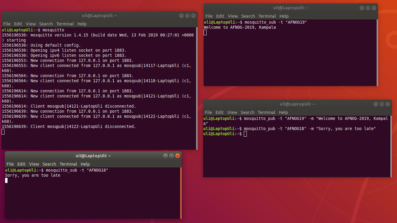
| < < | Below we see an example running the MQTT broker mosquitto, 2 nodes (mosquitto_sub) have subscribed to the topic AFNOG19 and AFNOG18 respectively.. When a third node publishes information on topic AFNOG19, then the first subscriber receives the information (payload) while when publishing on AFNOG18 it is the second subscriber seeing the message. | |||||||
| > > | Below we see an example running the MQTT broker mosquitto. Two nodes (mosquitto_sub) have subscribed to the topic AFNOG19 and AFNOG18 respectively.. When a third node publishes information on topic AFNOG19, then the first subscriber receives the information (payload) while when publishing on AFNOG18 it is the second subscriber seeing the message. | |||||||

MQTT and Cayenne | ||||||||
| Line: 27 to 27 | ||||||||
| Libraries in C, C++, Python, Java can be found on github. | ||||||||
| Changed: | ||||||||
| < < | Unfortunately the Cayenne MQTT Python library depends on the Eclipse Paho MQTT Python client, which is not available on Micropython. I therefore ported the Cayenne MQTT Client class to the simple.py MQTT client available in Micropython. The API is the same and the example programs should work without modification. | |||||||
| > > | Unfortunately, the Cayenne MQTT Python library depends on the Eclipse Paho MQTT Python client, which is not available on Micropython. I therefore ported the Cayenne MQTT Client class to the simple.py MQTT client available in micropython. The API is the same and the example programs should work without modification. | |||||||
| Changed: | ||||||||
| < < | The new Cayenne client package has already been integrated into Micropython such that you can make use of its classes and methods without any further installation.The source code has nevertheless been attached to this page for your inspection. Please remove the .txt extension after download to run the programs. | |||||||
| > > | The new Cayenne client package has already been integrated into micropython such that you can make use of its classes and methods without any further installation.The source code has nevertheless been attached to this page for your inspection. Please remove the .txt extension after download to run the programs. | |||||||
| https://afnog.iotworkshop.africa/pub/AFNOG/CommunicatingOverMQTT/clientPublic.py.txt | ||||||||
| Line: 37 to 37 | ||||||||
| https://afnog.iotworkshop.africa/pub/AFNOG/CommunicatingOverMQTT/ledControlPublic.py.txt | ||||||||
| Changed: | ||||||||
| < < | In order to use the package clientPublic.py.txt must be renamed to client.py and the Cayenne and WiFi credentials must be added. This program together with __init__.py must be stored in a directory called "cayenne". | |||||||
| > > | In order to use the package clientPublic.py.txt, it must be renamed to client.py and the Cayenne and WiFi credentials must be added. This program together with __init__.py must be stored in a directory called "cayenne". | |||||||
The example program | ||||||||
| Changed: | ||||||||
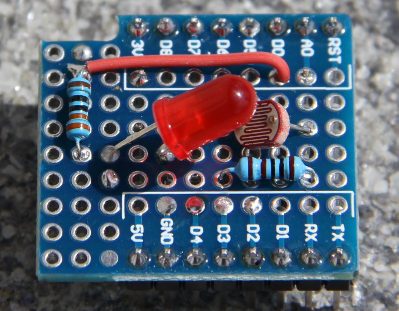
| < < | The example program uses hardware prepared for a simplistic demonstration IoT. It consists of a photo resistor in series with a 1kOhm resistor forming a voltage divider. The voltage over the photo resistor, changing with changing light intensity, is measured with the 10 bit ADC available on the ESP8266 and accessible on the A0 pin of the WeMos D1 mini CPU card. The measured voltage is published on channel 1. In addition to the photo resistor we have an LED shining on the photo resistor. This LED is connected to D0 on the WeMos D1 mini corresponding to GPIO 16 and can be controlled on channel 2. Finally the built-in LED on the CPU card, connected to D4 or GPIO 2 can be controlled through channel 3. | |||||||
| > > | The example program uses hardware prepared for a simplistic demonstration IoT. It consists of a photo-resistor in series with a 1kOhm resistor forming a voltage divider. The voltage over the photo-resistor, changing with changing light intensity, is measured with the 10 bit ADC available on the ESP8266 and accessible on the A0 pin of the WeMos D1 mini CPU card. The measured voltage is published on channel 1. In addition to the photo-resistor we have an LED shining on the photo-resistor. This LED is connected to D0 on the WeMos D1 mini corresponding to GPIO 16 and can be controlled on channel 2. Finally the built-in LED on the CPU card, connected to D4 or GPIO 2 can be controlled through channel 3. | |||||||
 | ||||||||
View topic | History: r5 < r4 < r3 < r2 | More topic actions...
Ideas, requests, problems regarding TWiki? Send feedback