Difference: HardwareAccessAndMicropython (1 vs. 7)
Revision 72019-06-11 - UliRaich
| Line: 1 to 1 | ||||||||
|---|---|---|---|---|---|---|---|---|
Slide 1: Setting up and IoT | ||||||||
| Line: 42 to 42 | ||||||||
How to program the processor | ||||||||
| Changed: | ||||||||
| < < |
| |||||||
| > > |
| |||||||
Flashing the code | ||||||||
| Line: 53 to 53 | ||||||||
esptool
| ||||||||
| Changed: | ||||||||
| < < |
| |||||||
| > > |
| |||||||
| In the above cases the use of esptool is hidden to us.
We can however also execute esptool directly. | ||||||||
| Line: 149 to 149 | ||||||||
| It is written in PyQt4 the Python language binding to Qt4. | ||||||||
| Changed: | ||||||||
| < < | The Linux version did not work for me | |||||||
| > > | The Linux version did not work for me when running Ubuntu 18.04 or later. | |||||||
| I found a version based on PyQt5 (new version of QT) which was even worse. | ||||||||
| Line: 251 to 251 | ||||||||
| ||||||||
| Changed: | ||||||||
| < < |
| |||||||
| > > |
| |||||||
| Changed: | ||||||||
| < < | WS2812B timing | |||||||
| > > | WS2812B timing | |||||||
|
For all the details on the ws2812b look at https://cdn-shop.adafruit.com/datasheets/WS2812B.pdf | ||||||||
| Line: 268 to 268 | ||||||||

| ||||||||
| Changed: | ||||||||
| < < | Cascading the WS2812B | |||||||
| > > | Cascading the WS2812B | |||||||
|
| ||||||||
| Line: 371 to 371 | ||||||||
The SHT30 digital temperature and relative humidity sensor | ||||||||
| Changed: | ||||||||
| < < | The SHT30 is a digital temperature and humidity sensor based on the I2C bus | |||||||
| > > | The SHT30 is a digital temperature and humidity sensor based on the I2C bus | |||||||
|
Here is its data sheet Temperature precision: +- 0.3 °C Relative humidity: +- 3 % Works on 2.4V – 5.5 V  | ||||||||
| Line: 398 to 398 | ||||||||
While for the course we only use the CPU and 2 sensor shields:
| ||||||||
| Changed: | ||||||||
| < < |
| |||||||
| > > |
| |||||||
| there are many more available on the market. We have a dozen such shields here for demo. All demo programs can be found at: https://github.com/uraich/MicroPython_IoTDemos
| ||||||||

Revision 62019-06-09 - UliRaich
| Line: 1 to 1 | ||||||||||
|---|---|---|---|---|---|---|---|---|---|---|
Slide 1: Setting up and IoT | ||||||||||
| Line: 391 to 391 | ||||||||||

| ||||||||||
| Added: | ||||||||||
| > > |
Where to find the demo code
While for the course we only use the CPU and 2 sensor shields:
| |||||||||
WeMos D1 mini sensor and actuator shields (1)
| ||||||||||
| Line: 405 to 416 | ||||||||||
| ||||||||||
| Added: | ||||||||||
| > > | Cost | |||||||||
| Added: | ||||||||||
| > > |  | |||||||||
Pinouts of shields | ||||||||||
| Line: 553 to 567 | ||||||||||
| ||||||||||
| Added: | ||||||||||
| > > |
| |||||||||


Revision 52019-05-14 - UliRaich
| Line: 1 to 1 | |||||||||||||||||||||||||||||||||||||||||||||||||||||||||
|---|---|---|---|---|---|---|---|---|---|---|---|---|---|---|---|---|---|---|---|---|---|---|---|---|---|---|---|---|---|---|---|---|---|---|---|---|---|---|---|---|---|---|---|---|---|---|---|---|---|---|---|---|---|---|---|---|---|
Slide 1: Setting up and IoT | |||||||||||||||||||||||||||||||||||||||||||||||||||||||||
| Changed: | |||||||||||||||||||||||||||||||||||||||||||||||||||||||||
| < < | Session 2: Micropython and | ||||||||||||||||||||||||||||||||||||||||||||||||||||||||
| > > | Session 2: Micropython and | ||||||||||||||||||||||||||||||||||||||||||||||||||||||||
The WeMos D1 mini CPU card
| |||||||||||||||||||||||||||||||||||||||||||||||||||||||||
| Line: 42 to 42 | |||||||||||||||||||||||||||||||||||||||||||||||||||||||||
How to program the processor | |||||||||||||||||||||||||||||||||||||||||||||||||||||||||
| Changed: | |||||||||||||||||||||||||||||||||||||||||||||||||||||||||
| < < |
| ||||||||||||||||||||||||||||||||||||||||||||||||||||||||
| > > |
| ||||||||||||||||||||||||||||||||||||||||||||||||||||||||
Flashing the code | |||||||||||||||||||||||||||||||||||||||||||||||||||||||||
| Line: 151 to 151 | |||||||||||||||||||||||||||||||||||||||||||||||||||||||||
| The Linux version did not work for me | |||||||||||||||||||||||||||||||||||||||||||||||||||||||||
| Changed: | |||||||||||||||||||||||||||||||||||||||||||||||||||||||||
| < < | I found a version based on PyQt5 (new version of QT) which was even worse. | ||||||||||||||||||||||||||||||||||||||||||||||||||||||||
| > > | I found a version based on PyQt5 (new version of QT) which was even worse. | ||||||||||||||||||||||||||||||||||||||||||||||||||||||||
| Changed: | |||||||||||||||||||||||||||||||||||||||||||||||||||||||||
| < < | I tried to correct as much as I could to make the PyQt5 version usable on Linux: | ||||||||||||||||||||||||||||||||||||||||||||||||||||||||
| > > | I tried to correct as much as I could to make the PyQt5 version usable on Linux: | ||||||||||||||||||||||||||||||||||||||||||||||||||||||||
|
https://github.com/uraich/uPyCraft-Qt5 | |||||||||||||||||||||||||||||||||||||||||||||||||||||||||
| Line: 295 to 294 | |||||||||||||||||||||||||||||||||||||||||||||||||||||||||
|
| |||||||||||||||||||||||||||||||||||||||||||||||||||||||||
| Added: | |||||||||||||||||||||||||||||||||||||||||||||||||||||||||
| > > | The I2C busI2C stands for Inter-Integrated-Circuit. It was invented by Philips Semiconductor in 1982. Slow, short distance. Quite a number of sensors in the "WeMos D1 sensor shield collection use the I2C bus
The physical busThe CPU (master) connects to the sensors (slaves) through
2 digital lines:
I2C start and stop sequence
When the master want to talk to the slave it issues a start sequence
I2C addressingWhen talking to a slave the master sends a seven bit address
followed by a read/write bit
I2C data transfer
Data is transmitted 8 bits at a time followed by an acknowledge bit.
I2C write cycle
I2C read cycle
I2C in Micropython
Scanning the I2C bus
The SHT30 digital temperature and relative humidity sensorThe SHT30 is a digital temperature and humidity sensor based on the I2C bus
Here is its data sheet
A look at the SHT30 driverhttps://afnog.iotworkshop.africa/pub/AFNOG/HardwareAccessAndMicropython/sht30.py.txt
Reading out the SHT30
Results from the SHT30
WeMos D1 mini sensor and actuator shields (1)
Wemos D1 mini sensor and actuator shields (2)
Pinouts of shields
Documentation for the demo programsDemo programs for all the shields are available on github:
https://github.com/uraich/MicroPython_IoTDemos A short description of every program can be found in the README
The data logger
The push button shield
DS18B20 shield
SSD1306 48x64 OLED displayThis one is also an I2C device
drawing methods of the framebuf are available for drawing:
https://github.com/uraich/MicroPython_IoTDemos/tree/master/drivers/oled
The DHT11 shield
The LED matrix
The buzzer
The prototype module
The triple base
This module allows to easily stack a rather larger number of shields to a sandwich.
ExercisesNow it is up toYouto do the work!
| ||||||||||||||||||||||||||||||||||||||||||||||||||||||||
| %SLIDESHOWEND% | |||||||||||||||||||||||||||||||||||||||||||||||||||||||||
| Line: 335 to 525 | |||||||||||||||||||||||||||||||||||||||||||||||||||||||||
| |||||||||||||||||||||||||||||||||||||||||||||||||||||||||
| Added: | |||||||||||||||||||||||||||||||||||||||||||||||||||||||||
| > > |
| ||||||||||||||||||||||||||||||||||||||||||||||||||||||||


Revision 42019-05-14 - UliRaich
| Line: 1 to 1 | |||||||||||||||||||||||||||||||||||||||||||||||
|---|---|---|---|---|---|---|---|---|---|---|---|---|---|---|---|---|---|---|---|---|---|---|---|---|---|---|---|---|---|---|---|---|---|---|---|---|---|---|---|---|---|---|---|---|---|---|---|
Slide 1: Setting up and IoT | |||||||||||||||||||||||||||||||||||||||||||||||
| Line: 41 to 41 | |||||||||||||||||||||||||||||||||||||||||||||||
How to program the processor | |||||||||||||||||||||||||||||||||||||||||||||||
| Changed: | |||||||||||||||||||||||||||||||||||||||||||||||
| < < |
| ||||||||||||||||||||||||||||||||||||||||||||||
| > > |
Flashing the code
esptool
We can however also execute esptool directly.
How to write a Micropython program?First we need a Micropython interpreter! You find the sources here:
https://github.com/micropython/micropython/ In the repository you find ports for the ESP8266 and the ESP32. In order to compile the code you need the ESP-IDF and its cross compilers The code compiles into a binary file (firmware-combined.bin) which contains a boot loader and the interpreter. This binary must be uploaded and flashed. For documentation of the ESP8266 port of Micropython look at
https://docs.micropython.org/en/latest/esp8266/tutorial/index.html
How to communicate with the Micropython interpreter?We use a serial connection passing through the micro USB connection. As soon as we connect the processor card to the PC we see the UART bridge and a new device: dev/ttyUSB0 is created. This device is used to communicate with the Micropython REPL.
You see the command prompt and you can interact with Micropython. But … how to upload scripts?
What is REPL?
The communication tools: minicom
You see the command prompt and you can interact with Micropython. But … how to upload scripts?
The command line tool ampy
IDE for Micropython: uPyCraft
uPyCraftuPyCraft is a rather complete Integrate Development Environment (IDE)
which lets you
Flashing MicropythonThis has already been done for you! However, it is easy if you want to do it at home with a new processor board. Compiling a new version of Micropython is substantially harder but also perfectly possible.
uPyCraft(2)uPyCraft is based on QT4 and is available for Linux, Windows and Mac. It is written in PyQt4 the Python language binding to Qt4. The Linux version did not work for me I found a version based on PyQt5 (new version of QT) which was even worse. I tried to correct as much as I could to make the PyQt5 version usable on Linux:
https://github.com/uraich/uPyCraft-Qt5
Thonny
Thonny (2)
Thonny is an IDE for Python which has provisions for Micropython. Python interpreter you intend to use.
IoT Hello World programA “Hello World” program, just printing “Hello World” on the screen does not look very exciting.
However, this is generally used to verify that the infrastructure and a blinking LED is used instead.
Switching on and off a LEDThe ESP8266 and the ESP32 have a “user LED” connected to GPIO 2.
How do we control this LED?
Micropython hardware functions
The machine.Pin class
Switch the LED on, version 1
Switch the LED on, version 2
The blinking LEDNow we put the code into a script and run it
Changing the light intensityThe LED is connected to a digital line which can only be set to 0 or Vcc. How can we change the light intensity and dim the LED? The light intensity depends on the average current flowing through the LED. The answer is PWM: pulse width modulation.
PWM in Micropython
Our PWM implementation
The WS2812B LED
A more complex LED:
WS2812B timing
For all the details on the ws2812b look at 24 bit of colour data puts 2e24 colours at your disposal Coding of a single bit
The control word:
Cascading the WS2812B
Using the neopixel library
… and our codeWe have a single neopixel connected to GPIO pin 4 (ESP8266) or GPIO pin 21 (ESP32) This code works on both CPUs!
| ||||||||||||||||||||||||||||||||||||||||||||||
| %SLIDESHOWEND% | |||||||||||||||||||||||||||||||||||||||||||||||
| Line: 60 to 312 | |||||||||||||||||||||||||||||||||||||||||||||||
| |||||||||||||||||||||||||||||||||||||||||||||||
| Added: | |||||||||||||||||||||||||||||||||||||||||||||||
| > > |
| ||||||||||||||||||||||||||||||||||||||||||||||


Revision 32019-05-14 - UliRaich
| Line: 1 to 1 | |||||||||||
|---|---|---|---|---|---|---|---|---|---|---|---|
| |||||||||||
| Deleted: | |||||||||||
| < < | Hardware access and Micropython | ||||||||||

| |||||||||||
| Changed: | |||||||||||
| < < |
Setting up an IoTSession 2: Micropython and
| ||||||||||
| > > | Setting up and IoTSession 2: Micropython and | ||||||||||
The WeMos D1 mini CPU card | |||||||||||
| Changed: | |||||||||||
| < < |
| ||||||||||
| > > |
| ||||||||||
| Changed: | |||||||||||
| < < | CPU PinOut
| ||||||||||
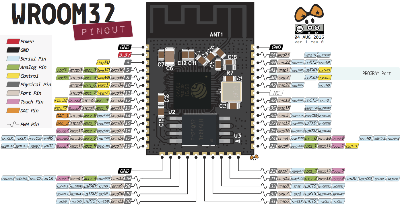
| > > | CPU Pinout
| ||||||||||
| |||||||||||
| Added: | |||||||||||
| > > | Please note: The pin numbers IOxx on the ESP32 correspond
to the GPIO pin numbers | ||||||||||
| Changed: | |||||||||||
| < < | Please note that the numbers IOxx for the ESP32 correspond to the GPIO numbers. | ||||||||||
| > > | The pins in the white fields go to the WeMos D1 mini bus | ||||||||||
| Changed: | |||||||||||
| < < | So..., IO22 corresponds to GPIO 22. | ||||||||||
| > > | and are also available on the ESP8266 | ||||||||||
| Changed: | |||||||||||
| < < | The same is not valid for the numbers Dx in the ESP8266 case. | ||||||||||
| > > | The other pins are only accessible on the ESP32 CPU card | ||||||||||
| Changed: | |||||||||||
| < < | Please see the next slide for the correspondence. | ||||||||||
| > > | The pin numbers Dx do not correspond to GPIO pin numbers!
Please refer to the next slide for correspondence | ||||||||||
|
| |||||||||||
| Changed: | |||||||||||
| < < | Comparison PinOut | ||||||||||
| > > | CPU pinouts for reference | ||||||||||
 | |||||||||||
| Added: | |||||||||||
| > > | Meaning of pins on ESP8266
Meaning of pins on ESP32
How to program the processor
| ||||||||||
| %SLIDESHOWEND% | |||||||||||
| Line: 41 to 55 | |||||||||||
| |||||||||||
| Changed: | |||||||||||
| < < |
| ||||||||||
| > > |
| ||||||||||


Revision 22019-05-13 - UliRaich
| Line: 1 to 1 | |||||||||||
|---|---|---|---|---|---|---|---|---|---|---|---|
Hardware access and Micropython | |||||||||||
| Changed: | |||||||||||
| < < | Here are the original slides: | ||||||||||
| > > |
| ||||||||||
| Changed: | |||||||||||
| < < | -- | ||||||||||
| > > | Setting up an IoTSession 2: Micropython and
| ||||||||||
 |
 |
| ESP8266 CPU | ESP32 CPU |
CPU PinOut
 |
 |
| ESP8266 | ESP32 |
Please note that the numbers IOxx for the ESP32 correspond to the GPIO numbers.
So..., IO22 corresponds to GPIO 22.
The same is not valid for the numbers Dx in the ESP8266 case.
Please see the next slide for the correspondence.
Comparison PinOut
ESP8266 versus ESP32 for reference
%SLIDESHOWEND%
Comments
>
| META FILEATTACHMENT | attachment="esp8266.png" attr="" comment="" date="1557779237" name="esp8266.png" path="esp8266.png" size="118895" user="UliRaich" version="1" |
|---|---|
| META FILEATTACHMENT | attachment="wemosEsp32.png" attr="" comment="" date="1557779391" name="wemosEsp32.png" path="wemosEsp32.png" size="218419" user="UliRaich" version="1" |
| META FILEATTACHMENT | attachment="cpuPinouts.png" attr="" comment="" date="1557779532" name="cpuPinouts.png" path="cpuPinouts.png" size="34918" user="UliRaich" version="1" |
| META FILEATTACHMENT | attachment="esp8266Pinout.png" attr="" comment="" date="1557780096" name="esp8266Pinout.png" path="esp8266Pinout.png" size="180678" user="UliRaich" version="1" |
| META FILEATTACHMENT | attachment="esp32Pinout.png" attr="" comment="" date="1557780235" name="esp32Pinout.png" path="esp32Pinout.png" size="318749" user="UliRaich" version="1" |
Revision 12019-05-13 - UliRaich
| Line: 1 to 1 | ||||||||
|---|---|---|---|---|---|---|---|---|
| Added: | ||||||||
| > > |
Hardware access and MicropythonHere are the original slides:
Comments
| |||||||
Ideas, requests, problems regarding TWiki? Send feedback