Difference: HardwareAccessGPIO (4 vs. 5)
Revision 52022-10-23 - UliRaich
| Line: 1 to 1 | |||||||||||||
|---|---|---|---|---|---|---|---|---|---|---|---|---|---|
Hardware access, the General Purpose Input Output (GPIO) pins.Running the programs on the PC | |||||||||||||
| Line: 12 to 13 | |||||||||||||
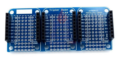
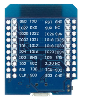
| The connection of digital input or output signals is made through General Purpose Input Output pins. These pins can be programmed to output (control) a signal level or to input (acquire) a signal level. The base board and the back of the CPU card look like this (the pins on the ESP32 CPU are mirrored with respect to the base board): | |||||||||||||
| Changed: | |||||||||||||
| < < |
| ||||||||||||
| > > |
| ||||||||||||
| |||||||||||||
| Changed: | |||||||||||||
| < < | As you can see, the pins on the triple board are marked | ||||||||||||
| > > | As you can see, the pins on the triple board are marked, as are the ones on the ESP32 COU board. Please note that the pins on the CPU card are mirrored. | ||||||||||||
| |||||||||||||
| Line: 72 to 74 | |||||||||||||
| I think we are ready for another exercise session ExerciseSheets#ThirdSession | |||||||||||||
| Changed: | |||||||||||||
| < < | In the next step, we will read analogue signal levels: AnalogSignals | ||||||||||||
| > > | In the next step, we will read analogue signal levels: Analogue Signals | ||||||||||||
|
-- | |||||||||||||
View topic | History: r5 < r4 < r3 < r2 | More topic actions...
Ideas, requests, problems regarding TWiki? Send feedback

