Difference: TheHardware (12 vs. 13)
Revision 132020-10-12 - UliRaich
| Line: 1 to 1 | ||||||||
|---|---|---|---|---|---|---|---|---|
The HardwareThe CPU card | ||||||||
| Line: 16 to 16 | ||||||||
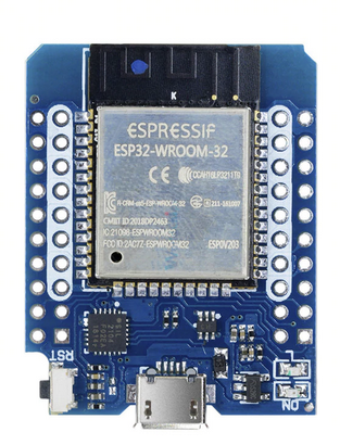
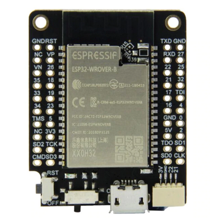
Here are photos of the boards:
| ||||||||
| Changed: | ||||||||
| < < | For more details please read the data sheet: | |||||||
| > > | For more details, please read the datasheet: | |||||||
| https://afnog.iotworkshop.africa/pub/IoT_Course_English/TheHardware/esp32-wroom-32_datasheet_en.pdf | ||||||||
| Line: 30 to 30 | ||||||||
| While the ESP32-wroom-32 uses GPIO 2 for its on-board user LED the ESP32-wrover-b uses GPIO 19. | ||||||||
| Changed: | ||||||||
| < < | The ESP32-wrover-b has a design flaw: GPIO 16 connected to pin D3 and GPIO 17 connected to pin D4 cannot be used to control sensors because these GPIO lines are used to control the PSRAM. This means that the CPU is incompatible with any shield using pins D3 and D4. Other GPIO lines should have been made available instead. | |||||||
| > > | The ESP32-wrover-b has a design flaw: GPIO 16 connected to pin D3 and GPIO 17 connected to pin D4 cannot be used to control sensors because these GPIO lines are used to control the PSRAM. This means that the CPU is incompatible with any shield using pins D3 and D4. According to the LilyGo (provider of the CPU board) engineer GPIO 25 can be jumpered to D3 (GPIO 16) and GPIO 4 can be jumpered to D4 (GPIO 16). Doing this will allow to use the bus lines on the new GPIO connections. | |||||||
| Changed: | ||||||||
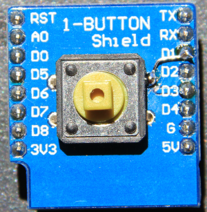
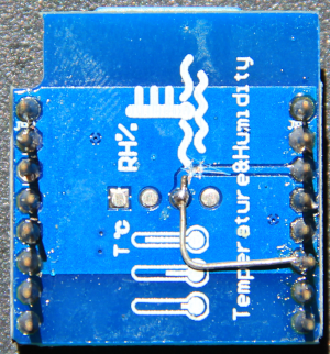
| < < | Checking the hardware table below shows that only the push button shield (D3) and the DHT11 (D4) use the forbidden pins. I therefore made hardware patches to connect their forbidden pins to D1. | |||||||
| > > | Checking the hardware table below shows that only the push button shield (D3) and the DHT11 (D4) use the forbidden pins. I therefore made hardware patches to connect their forbidden pins to D1. Having had the LilyGo information before I could have left the boards unchanged and added jumpers to the CPU board. | |||||||
The Base Board | ||||||||
| Changed: | ||||||||
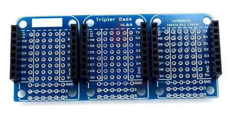
| < < | This board has no active elements but it connects sensor shields to the CPU board. Like this the necessary connections are made in a Lego based manner by just plugging modules together without any further cable connections or soldering. | |||||||
| > > | This board has no active elements, but it connects sensor shields to the CPU board. The connections are made in a Lego-based manner by just plugging modules together without any further cable connections or soldering. | |||||||
Switches | ||||||||
| Line: 49 to 49 | ||||||||
LEDs | ||||||||
| Changed: | ||||||||
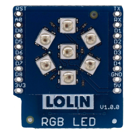
| < < | On the CPU card there is a user programmable LED which is used in the exercise on LEDs. This is a simple, single color (blue) LED. In the series of shields we can also find an LED chain with 7 addressable WS2812 RGB LEDs. | |||||||
| > > | On the CPU card, there is a user programmable LED, used in the exercise on LEDs. This is a simple, single color (blue) LED. In the series of shields, we can also find an LED chain with 7 addressable WS2812 RGB LEDs. | |||||||
Temperature and Humidity Sensors and Barometric Pressure Sensor | ||||||||
| Changed: | ||||||||
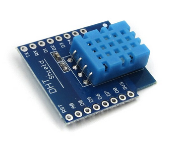
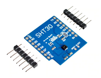
| < < | There are several different environmental sensors of which we will use the DHT11 and the SHT30 temperature and humidity sensors. We work with both sensors in different exercises because these shields use quite different communication protocols which we want to study. | |||||||
| > > | There are several environmental sensors of which we will use the DHT11 and the SHT30 temperature and humidity sensors. We work with both sensors in the exercises because these shields use quite different communication protocols, which we want to study. | |||||||
| Changed: | ||||||||
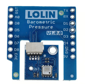
| < < | In addition to the temperature and humidity sensors we have a barometric pressure sensor, (which also allows to measure ambient temperature) the BMP180. With these 3 sensors we can construct a simple weather station. | |||||||
| > > | In addition to the temperature and humidity sensors, we have a barometric pressure sensor, (which also allows to measure ambient temperature) the BMP180. With these 3 sensors, we can construct a simple weather station. | |||||||
Real Time Clock and Data Logging | ||||||||
| Changed: | ||||||||
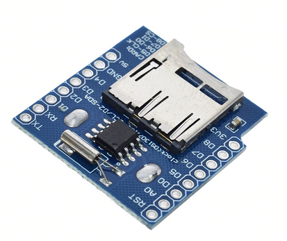
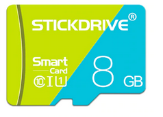
| < < | In order to store data taken with the environmental sensors we us a micro SD card supplied with the Real Time Clock and Data Logger card. With the Real Time Clock we can get a time stamp telling us when the data have been taken. | |||||||
| > > | In order to store data taken with the environmental sensors, we us a micro SD card supplied with the Real-Time Clock and Data Logger card. With the Real-Time Clock we can get a time stamp, telling us when the data have been taken. | |||||||
Displays | ||||||||
| Changed: | ||||||||
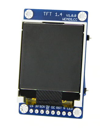
| < < | Of course we can transfer the measurement data to a PC over the Internet and use the plotting facilities on the PC to graphically show the data but it may sometimes be interesting to show the data also on the micro-controller without the need of an Internet access. This can be done with TFT screen sensors. The one we will use has a resolution of 128*128 pixels and text as well as simple pixel based graphics is possible with these devices. | |||||||
| > > | Of course we can transfer the measurement data to a PC over the Internet and use the plotting facilities on the PC to graphically present the data but it may sometimes be interesting to show the data also on the micro-controller, without the need of Internet access. This is possible with TFT screens. The screeen we will use has a resolution of 128*128 pixels and text as well as simple pixel-graphics is possible with these devices. | |||||||
Motors | ||||||||
| Changed: | ||||||||
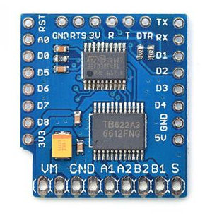
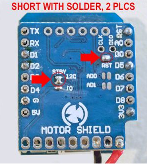
| < < | You can also control different types of motors with the ESP32. To demonstrate this we use the motor controller shield. | |||||||
| > > | You can also control different types of motors with the ESP32. To demonstrate this, we use the motor controller shield. | |||||||
| ||||||||
View topic | History: r24 < r23 < r22 < r21 | More topic actions...
Ideas, requests, problems regarding TWiki? Send feedback
