
Slide 1: Setting up and IoT
Session 2: Micropython and
Hardware access
Uli Raich
Formally CERN, Geneva, Switzerland
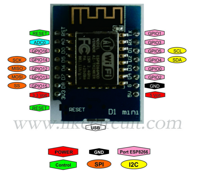
Slide 2: The WeMos D1 mini CPU card
 |
 |
| ESP8266 cost: 2.21 Euros |
ESP32 cost: 4.1o Euros |
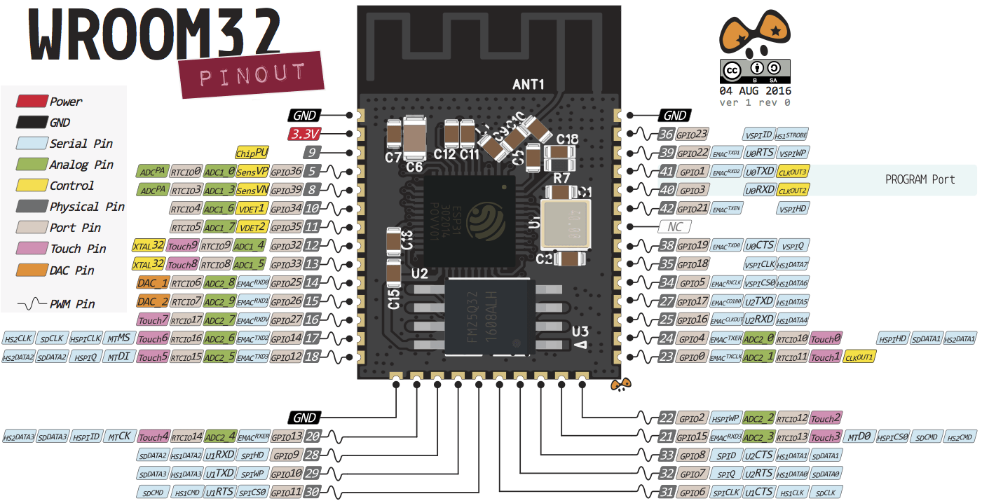
Slide 3: CPU Pinout
 |
 |
| ESP8266 | ESP32 |
Slide 4: CPU pinouts for reference

Slide 5: Meaning of pins on ESP8266
|
 |
Slide 6: Meaning of pins on ESP32
Slide 7: How to program the processor
 |
Several development tools are available:
Please see
see:
see: |
Slide 8: Flashing the code

Slide 9: esptool
- esptool is called from the Makefiles in ESP-IDF
- esptool is used when we upload code from the Arduino IDE to the processor flash
- esptool is used when the Micropython IDE uPyCraft
installs Micropython onto the processor flash
Slide 10: How to write a Micropython program?
First we need a Micropython interpreter! You find the sources here: https://github.com/micropython/micropython/Slide 11: How to communicate with the Micropython interpreter?
We use a serial connection passing through the micro USB connection. As soon as we connect the processor card to the PC we see the UART bridge and a new device: dev/ttyUSB0 is created. This device is used to communicate with the Micropython REPL. You see the command prompt and you can interact with Micropython. But
how to upload scripts?
You see the command prompt and you can interact with Micropython. But
how to upload scripts?
Slide 12: What is REPL?

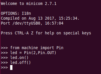
Slide 13: The communication tools: minicom
 You see the command prompt and you can interact with Micropython.
But
how to upload scripts?
You see the command prompt and you can interact with Micropython.
But
how to upload scripts?
Slide 14: The command line tool ampy

Slide 15: IDE for Micropython: uPyCraft

Slide 16: uPyCraft
uPyCraft is a rather complete Integrate Development Environment (IDE) which lets you- Access the REPL
- Create directories on the Micropython file system
- Upload scripts
- Syntax check scripts
- Run scripts
- Install Micropython on your processor board
Slide 17: Flashing Micropython
This has already been done for you! However, it is easy if you want to do it at home with a new processor board. Compiling a new version of Micropython is substantially harder but also perfectly possible.
Slide 18: uPyCraft(2)
uPyCraft is based on QT4 and is available for Linux, Windows and Mac. It is written in PyQt4 the Python language binding to Qt4. The Linux version did not work for me I found a version based on PyQt5 (new version of QT) which was even worse. I tried to correct as much as I could to make the PyQt5 version usable on Linux: https://github.com/uraich/uPyCraft-Qt5Slide 19: Thonny

Slide 20: Thonny (2)
Thonny is an IDE for Python which has provisions for Micropython.Under Tools → Options button you can select the type of Python interpreter you intend to use.

Slide 21: IoT Hello World program
A Hello World program, just printing Hello World on the screen does not look very exciting. However, this is generally used to verify that the infrastructureCompiler, linker, downloader, flash program
are working correctly
In embedded systems printing can be quite complex and a blinking LED is used instead.
Slide 22: Switching on and off a LED
The ESP8266 and the ESP32 have a user LED connected to GPIO 2. How do we control this LED?- Define that the LED is connected to GPIO 2
- Program this pin as output
- Write a logic 1 to the pin to switch it on
- Write a logic 0 to the pin to switch it off
- The logic state may be inverted if the LED is active low
Slide 23: Micropython hardware functions

Slide 24: The machine.Pin class

Slide 25: Switch the LED on, version 1

Slide 26: Switch the LED on, version 2

Slide 27: The blinking LED
Now we put the code into a script and run it
Slide 28: Changing the light intensity
The LED is connected to a digital line which can only be set to 0 or Vcc. How can we change the light intensity and dim the LED? The light intensity depends on the average current flowing through the LED. The answer is PWM: pulse width modulation.
Slide 29: PWM in Micropython

Slide 30: Our PWM implementation

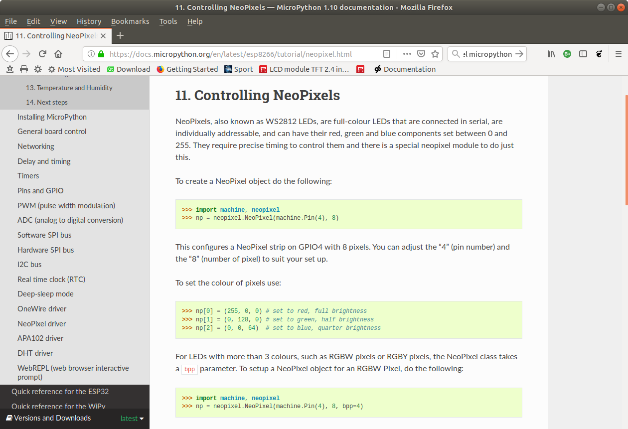
Slide 31: The WS2812B LED
A more complex LED:- rgb LED used in LED chains.
- each ws18b12 contains the 3 colored LEDs and a controller.
- Can be cascaded and individually addressed, depending on its position in the chain
- Needs precise timing
- To use it we pass through the neopixel library built into MicroPython
Slide 32: WS2812B timing
For all the details on the ws2812b look athttps://cdn-shop.adafruit.com/datasheets/WS2812B.pdf
 The control word:

Slide 33: Cascading the WS2812B

Slide 34: Using the neopixel library
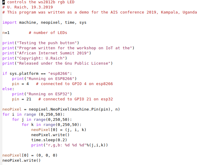
Slide 35: and our code
We have a single neopixel connected to GPIO pin 4 (ESP8266) or GPIO pin 21 (ESP32) This code works on both CPUs!Comments


| I | Attachment |
History | Action | Size | Date | Who | Comment |
|---|---|---|---|---|---|---|---|
| |
afnog19-ws-session2.odp | r1 | manage | 6431.5 K | 2019-05-14 - 09:01 | UliRaich | |
| |
ampy.png | r1 | manage | 100.7 K | 2019-05-14 - 11:42 | UliRaich | |
| |
blinkingLed.png | r1 | manage | 79.9 K | 2019-05-14 - 12:17 | UliRaich | |
| |
cpuPinouts.png | r1 | manage | 34.1 K | 2019-05-13 - 20:32 | UliRaich | |
| |
esp32-pinout-chip-ESP-WROOM-32.png | r1 | manage | 137.4 K | 2019-05-14 - 09:50 | UliRaich | |
| |
esp32Pinout-v2.png | r1 | manage | 151.2 K | 2019-05-14 - 09:01 | UliRaich | |
| |
esp8266.png | r1 | manage | 116.1 K | 2019-05-13 - 20:27 | UliRaich | |
| |
esp8266PinMeaning.png | r2 r1 | manage | 155.3 K | 2019-05-14 - 09:43 | UliRaich | |
| |
esp8266Pinout.png | r1 | manage | 176.4 K | 2019-05-13 - 20:41 | UliRaich | |
| |
esp8266Programming.png | r1 | manage | 108.3 K | 2019-05-14 - 09:59 | UliRaich | |
| |
esptool.png | r1 | manage | 114.3 K | 2019-05-14 - 11:28 | UliRaich | |
| |
hardwareFunctions.png | r1 | manage | 159.5 K | 2019-05-14 - 12:17 | UliRaich | |
| |
ledControl1.png | r1 | manage | 19.8 K | 2019-05-14 - 12:17 | UliRaich | |
| |
ledControl2.png | r1 | manage | 19.8 K | 2019-05-14 - 12:18 | UliRaich | |
| |
lsusb.png | r1 | manage | 73.3 K | 2019-05-14 - 11:48 | UliRaich | |
| |
minicom.png | r1 | manage | 17.2 K | 2019-05-14 - 11:42 | UliRaich | |
| |
neopixel.png | r1 | manage | 165.5 K | 2019-05-14 - 12:46 | UliRaich | |
| |
neopixelCode.png | r1 | manage | 79.9 K | 2019-05-14 - 12:46 | UliRaich | |
| |
pinClass.png | r1 | manage | 160.1 K | 2019-05-14 - 12:20 | UliRaich | |
| |
pinControl2.png | r1 | manage | 19.8 K | 2019-05-14 - 12:18 | UliRaich | |
| |
pwm_uP.png | r1 | manage | 24.6 K | 2019-05-14 - 12:31 | UliRaich | |
| |
pwm.png | r1 | manage | 51.4 K | 2019-05-14 - 12:27 | UliRaich | |
| |
pwmImpl.png | r1 | manage | 116.7 K | 2019-05-14 - 12:31 | UliRaich | |
| |
repl.png | r1 | manage | 20.2 K | 2019-05-14 - 11:45 | UliRaich | |
| |
thonny_uP.png | r1 | manage | 31.0 K | 2019-05-14 - 12:05 | UliRaich | |
| |
thonny.png | r1 | manage | 148.1 K | 2019-05-14 - 12:05 | UliRaich | |
| |
updateFirmware.png | r1 | manage | 27.3 K | 2019-05-14 - 11:59 | UliRaich | |
| |
uPyCraft.png | r1 | manage | 164.1 K | 2019-05-14 - 11:43 | UliRaich | |
| |
wemosEsp32.png | r1 | manage | 213.3 K | 2019-05-13 - 20:29 | UliRaich | |
| |
ws2812Bits.png | r1 | manage | 11.9 K | 2019-05-14 - 12:42 | UliRaich | |
| |
ws2812Chain.png | r1 | manage | 19.9 K | 2019-05-14 - 12:42 | UliRaich | |
| |
ws2812ControlWord.png | r1 | manage | 7.6 K | 2019-05-14 - 12:42 | UliRaich |

Ideas, requests, problems regarding TWiki? Send feedback