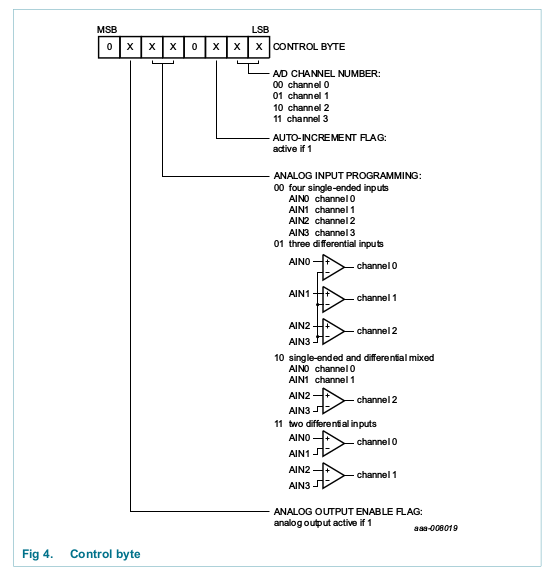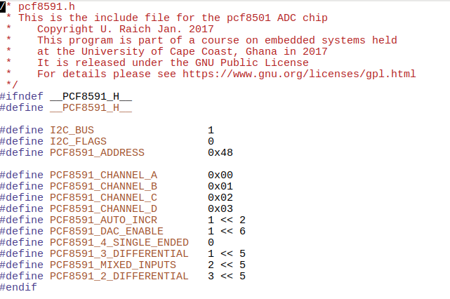
In our sensor kit we have 2 different small printed circuit boards
with Analogue to Digital Converters (ADCs) on board:
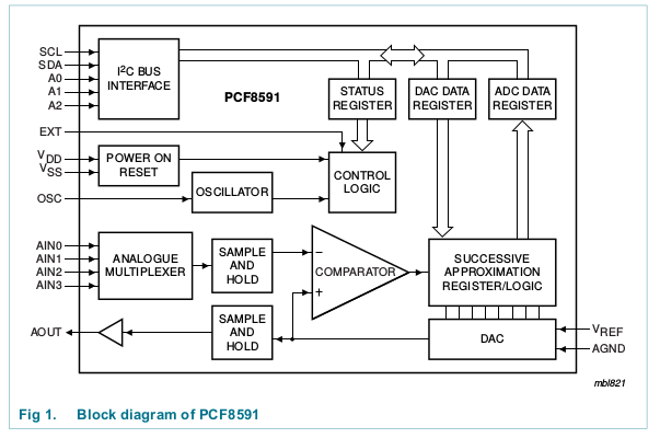
- The PCF8591 4 channel, 8 bit successive approximation ADC
- The ADS1115 4 channel 16b bit ΣΔ ADC
In my treasure box I also have a few mcp3004 ADC chips,
which are 10 bit converters providing sampling rates of up to
200ksps (kilo samples per second)
These devices use the SPI interface which will not be explained in this course.
However, you are invited to read the data sheet and to try them.
If you want to play on higher frequency ADCs, then we have a
48 MHz ADC, which is employed in the Hantek 6022BE DSO
(Digital Storage Oscilloscope)
Today we have 14 bit ADCs with sampling rate in the GHz range.
Why do we use the PCF8591 ADC, which is the device with
the worst characteristics?
- Only 8 bit resolution
- Conversion rate determined by I2C bus frequency (100 kbps)
- Has four multiplexed input channels
- Has one 8 bit DAC channel
- We do not need a high precision or super fast AD conversion,
which gives us a resolution of better than 1/2 % full range - We are only interested to understand the principle of A to D conversion
- Having analogue devices on the PCB allowing us
to test our setup is and important asset
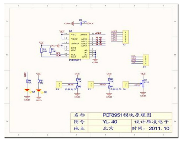
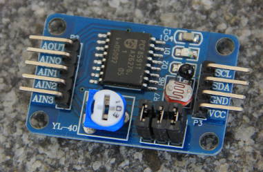
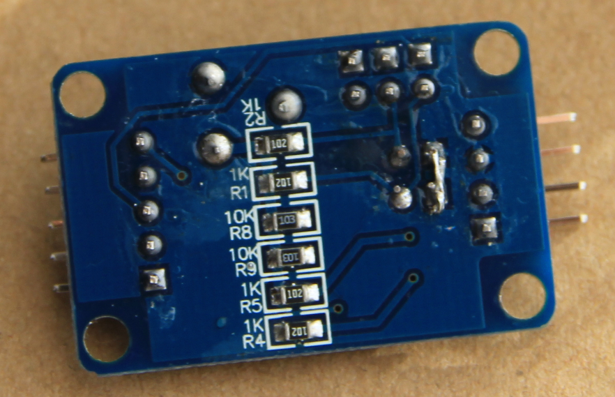
There were 2 problems with the YL-40 board I bought from China:
- The connection of one end of the thermistor to ground was
missing and had to be added by soldering a short connection. - The DAC output does not reach Vdd of full scale because
the LED connected to it draws too much current.
As we can see from the photos and from the circuit diagrams,
the YL-40 has already 3 devices that can be connected
to the PCF8591 inputs through jumpers:
- a photo resistor (AIN0)
- a thermistor (AIN1)
- a potentiometer (AIN3)
Set the DAC value to Vcc/2 (½ of 0-Vcc interval)
and compare with analogue signal level
If signal level > DAC, set bit 7 to 1 and set DAC level to ¾ Vcc
else set bit 7 to 0 and set DAC level to ¼ Vcc
If signal level > DAC level set bit 6 to 1 and
set DAC level to ½ of the upper interval
else
set bit 6 to 0 and DAC leve to ½ of lower interval
After 8 approximations we have the converted 8 bit value
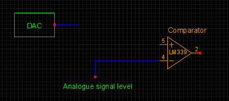

Once you have initialized the pigpio library with
- pigpio_start
- i2c_open
- controlByte =PCF8591_CHANNEL_C | PCF8591_4_SINGLE_ENDED;
i2c_write_byte(pi,handle,controlByte;
- adcValue=i2c_read_byte(pi,handle);
Students typically have problems with
- Pointers
- Parameter passing
What has happened to the pointer during the loop?
 It has advanced and now points to the zero string terminator.
Subtracting the old value (hello) from the
new helloPtr value yields the string length

 It has advanced and now points to the zero string terminator.
Subtracting the old value (hello) from the
new helloPtr value yields the string length
If instead of printing the character pointed to by the helloPtr wit "%c"
we print the (remaining) string with "%s"
 this is what we will see:
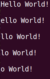 Here is the source code of the example programs:
https://afnog.iotworkshop.africa/pub/Embedded_Systems/Lecture12:AnalogueToDigitalConversion/pointers.tar.gz
 this is what we will see:
 Here is the source code of the example programs:
https://afnog.iotworkshop.africa/pub/Embedded_Systems/Lecture12:AnalogueToDigitalConversion/pointers.tar.gz


--
Comments
| I | Attachment | History | Action | Size | Date | Who | Comment |
|---|---|---|---|---|---|---|---|
| |
Screenshot_from_2017-11-14_12-11-57.png | r1 | manage | 215.0 K | 2017-11-21 - 08:06 | UnknownUser | |
| |
controlByte.png | r1 | manage | 33.8 K | 2017-11-21 - 08:05 | UnknownUser | |
| |
derefRes.png | r1 | manage | 41.6 K | 2017-11-21 - 08:05 | UnknownUser | |
| |
dereference.png | r1 | manage | 42.1 K | 2017-11-21 - 08:05 | UnknownUser | |
| |
includeFile.png | r1 | manage | 42.4 K | 2017-11-21 - 08:05 | UnknownUser | |
| |
pcf8591.png | r1 | manage | 209.7 K | 2017-11-21 - 08:12 | UnknownUser | |
| |
pcf8591BlockDiag.png | r1 | manage | 35.3 K | 2017-11-21 - 08:05 | UnknownUser | |
| |
pcf8591backcorrected.png | r1 | manage | 765.1 K | 2017-11-21 - 08:12 | UnknownUser | |
| |
pointerLoop.png | r1 | manage | 5.9 K | 2017-11-21 - 08:48 | UnknownUser | |
| |
pointerVal.png | r1 | manage | 10.2 K | 2017-11-21 - 08:05 | UnknownUser | |
| |
pointer_assignment.png | r1 | manage | 13.4 K | 2017-11-21 - 08:05 | UnknownUser | |
| |
pointers.tar.gz | r1 | manage | 6.9 K | 2017-11-23 - 15:48 | UnknownUser | |
| |
pot.png | r1 | manage | 6.7 K | 2017-11-21 - 08:05 | UnknownUser | |
| |
remain.png | r1 | manage | 5.6 K | 2017-11-21 - 08:06 | UnknownUser | |
| |
remainRes.png | r1 | manage | 4.6 K | 2017-11-21 - 08:06 | UnknownUser | |
| |
stringLoop.png | r1 | manage | 5.6 K | 2017-11-21 - 08:53 | UnknownUser | |
| |
strlen.png | r1 | manage | 10.1 K | 2017-11-21 - 08:06 | UnknownUser | |
| |
successiveAppr.png | r1 | manage | 6.8 K | 2017-11-21 - 08:06 | UnknownUser | |
| |
updatePtr.png | r1 | manage | 5.9 K | 2017-11-21 - 08:06 | UnknownUser | |
| |
yl-40.png | r1 | manage | 215.0 K | 2017-11-21 - 08:07 | UnknownUser |
This topic: Embedded_Systems > WebHome > LectureSlides > Lecture12:AnalogueToDigitalConversion
Topic revision: r2 - 2017-11-23 - uli
Ideas, requests, problems regarding TWiki? Send feedback


