

| I | Attachment | History | Action | Size | Date | Who | Comment |
|---|---|---|---|---|---|---|---|
| |
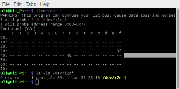
i2cdetect.png | r1 | manage | 29.3 K | 2017-02-01 - 11:59 | UnknownUser |

|
|
|
|
Ideas, requests, problems regarding TWiki? Send feedback
| I | Attachment | History | Action | Size | Date | Who | Comment |
|---|---|---|---|---|---|---|---|
| |
i2cdetect.png | r1 | manage | 29.3 K | 2017-02-01 - 11:59 | UnknownUser |
|
|
|
|