Tags:
view all tags
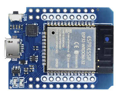
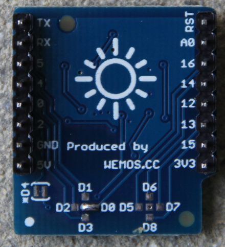
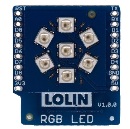
---+ !LEDs and !NeoPixel ---++ Introduction The ESP32 has 2 !LEDs on board. The first one indicates power while the second one is user programmable. The user programmable built-in !LED is connected to !GPIO pin 2. <img alt="esp32.png" height="313" src="%ATTACHURL%/esp32.png" title="esp32.png" width="410" /> You can see the !LEDs in the far left, bottom corner. The power !LED is marked "ON" while the user programmable one is marked "L". The !NeoPixel is based on the WS2812 addressable !RGB !LED which is often used in !LED chains. In our case we have 6 !LEDs arranged in a ring with a 7th one placed in the center of the ring. | *WS2812 LEDs front* | *WS2812 LEDs back* | | <img alt="leds.png" height="440" src="%ATTACHURL%/leds.png" title="leds.png" width="444" /> | <img alt="ledRingBack.png" height="483" src="%ATTACHURL%/ledRingBack.png" title="ledRingBack.png" width="440" /> | Again the !LEDs are accessible, this time through a dedicated serial protocol, on a single GPIO line. For the board we are using the !GPIO line can be selected with solder jumpers. If you look at the photo of the board's back side very closely you will see that the jumper was set to D0 or GPIO 26 on the ESP32. ---++ Further introductory remarks: In comparison with the first exercise session these exercises are rather simple. This is mainly due to the fact that all difficulties in accessing the devices are hidden from you in the drivers which are part of !MicroPython. If you want to know what is going on behind the scene please have a look at https://www.parallax.com/sites/default/files/downloads/28085-WS2812B-RGB-LED-Datasheet.pdf ---++ Exercise 1: Switching the user !LED with !REPL It is actually very easy to access the !LED because all you need is already available in !MicroPython. Just look it up at <br /> [[https://docs.micropython.org/en/latest/esp32/quickref.html#pins-and-gpio][https://docs.micropython.org/en/latest/esp32/quickref.html#pins-and-gpio ]]and try the example using !GPIO pin 2. Don't write a script just yet but switch the !LED on and off with REPL. ---++ Exercise 2: The Embedded System's Hello World Program: The blinking !LED Write a script that makes the !LED blink at 1 Hz (500ms on, 500 ms off). Improve the program by capturing Ctrl-C, which stops the endless loop, switching off the !LED before exiting the program. This can easily be done in a _try..except_ clause capturing the<i> !KeyboardInterrupt</i> exception. ---++ Exercise 3: SOS Probably the most well known Morse sequence is SOS (Save Our Souls) which consists of 3 long sounds (Morse "S") followed by 3 short ones (Morse "O") again followed by 3 long ones. Make the !LED blink the SOS sequence. Pause for 1 s between 2 SOS sequences. ---++ Exercise 4: Change the !LED light intensity The light intensity on the LED can be changed if we do not supply a fixed signal level to it but a frequency. The duty cycle of the signal determines the light intensity. This is called <b>P</b>ulse <b>W</b>idth <b>M</b>odulation or PWM for short. Write a program that increases the intensity in a linear fashion and the decreases it again linearly. -- %USERSIG{UliRaich - 2020-05-05}% ---++ Exercise 5: The WS2812 addressable LED The WS2812 LED is often used in LED chains. It is an RGB LED using a single data line which can be cascaded. It has a _data in_ pin and a _data out_ pin where the _data out_ pin is connected to the _data in pin_ of the following LED. It uses a serial protocol that must be precisely timed. For more information please consult the [[https://www.parallax.com/sites/default/files/downloads/28085-WS2812B-V4_v1.0-RGB-LED-Datasheet.pdf][data sheet]]. Fortunately a [[https://docs.micropython.org/en/latest/esp32/quickref.html#neopixel-driver][driver for the WS2812]] running on the ESP32 is already integrated into the !MicroPython binary. <b>Warning: </b>The WS2812 produces very bright light! Do not look into it directly or reduce the light intensity by software. The RGB LED chain has 7 LEDs installed on its PCB. Write a program that allows you to find out which LED corresponds to which address. To do so, please switch on a single LED e.g. its red component, and print out the corresponding address. Wait for 5s before you switch on the next LED. Only a single LED should light for each of the seven addresses. ---++ Exercise 6: Change the Colors Write a program that consecutively switches on the LEDs in different colors. First switch on the red component of the LED with address 0 then add the one with address 1 etc. Once all LEDs are red, switch them off again, change the color to green and repeat the cycle. Finally do the same for the blue component. Wait for 1 s before switching the LEDs. ---++ Exercise 7: Change to CCW In exercise 6 the LEDs will turn on clockwise (cw). Modify the program such that the LEDs turn on counter clock wise (ccw). ---++ Comments %COMMENT%
Attachments
Attachments
Topic attachments
I
Attachment
History
Action
Size
Date
Who
Comment
png
esp32.png
r1
manage
225.8 K
2020-05-05 - 18:42
UliRaich
png
ledRingBack.png
r1
manage
348.5 K
2020-05-22 - 07:50
UliRaich
png
leds.png
r1
manage
292.6 K
2020-05-05 - 18:40
UliRaich
Edit
|
Attach
|
Watch
|
P
rint version
|
H
istory
:
r8
<
r7
<
r6
<
r5
<
r4
|
B
acklinks
|
V
iew topic
|
Raw edit
|
More topic actions...
Topic revision: r5 - 2020-05-22
-
UliRaich
Home
Site map
AFNOG web
Embedded_Systems web
IoT_Course_English web
IoT_Course_French web
Main web
Sandbox web
TWiki web
IoT_Course_English Web
Create New Topic
Index
Search
Changes
Notifications
RSS Feed
Statistics
Preferences
P
View
Raw View
Print version
Find backlinks
History
More topic actions
Edit
Raw edit
Attach file or image
Edit topic preference settings
Set new parent
More topic actions
Account
Log In
Register User
Edit
Attach
Copyright © 2008-2025 by the contributing authors. All material on this collaboration platform is the property of the contributing authors.
Ideas, requests, problems regarding TWiki?
Send feedback


