Difference: ST7735TFTDisplay (6 vs. 7)
Revision 72020-07-28 - UliRaich
| Line: 1 to 1 | |||||||||||
|---|---|---|---|---|---|---|---|---|---|---|---|
Exercise 10: A TFT Display and the ST7735 display controllerIntroduction | |||||||||||
| Line: 19 to 19 | |||||||||||
 | |||||||||||
| Added: | |||||||||||
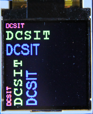
| > > | The font files are actually executable Python code that you can run on CPython on your laptop. Try to run e.g. courier20.py and sysfont.py. You will see a letter, which in case of the courier font will be upright(hmap() returns true), while in the sysfont case it will be turned clockwise by 90 ° (hmap() returns false). Can you write a piece of code that will transform the sysfont glyph into an upright layout? | ||||||||||
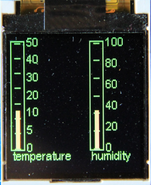
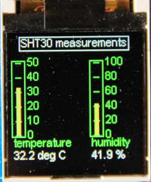
Exercise 3: Graphical User Interface (GUI) elements from nanoguiCreate 2 meters, one for temperature (0..50) and one for humidity (0..100). Generate dummy temperature and humidity values and display them in the meters. | |||||||||||
| Changed: | |||||||||||
| < < |  | ||||||||||
| > > | Once the graphics works replace the dummy measurements by real ones from the SHT30.
| ||||||||||
| Deleted: | |||||||||||
| < < | Replace the dummy measurements by real ones from the SHT30.
 | ||||||||||
Exercise 4: PlotsCreate a plot of a damped oscillator | |||||||||||
| Line: 36 to 35 | |||||||||||
Exercise 5: A new GUI element (bonus point)Create a new "scale" GUI element showing a scale. This should can be used e.g. to create a Voltmeter making use of the ESP32 ADC. | |||||||||||
| Changed: | |||||||||||
| < < | Exercise 6: Mario, a real challenge! | ||||||||||
| > > | Exercise 6: Super Mario, a bit of a challenge!Two simple arcade games come with the SD1351 driver demos. One of them is a Super Mario game, which however is based on hardware we don't have. As far as I can see they use a joystick with BlueTooth connection. You can replace this with an analogue joystick we have in our sensor box. 2 ADC channels are needed to read it out. | ||||||||||
| Changed: | |||||||||||
| < < | Two simple arcade games come with the SD1351 driver demos. One of them is a Super Mario game, which however is base on hardware we don't have. Can you modify the code such that you can run the program with the hardware we have (e.g the analogue joystick)? | ||||||||||
| > > | Here are the connections:
| ||||||||||
-- Comments | |||||||||||
View topic | History: r12 < r11 < r10 < r9 | More topic actions...
Ideas, requests, problems regarding TWiki? Send feedback