
Slide 1: Accessing sensors and actuators
Session 2 of the AFNOG tutorial
on IoT sensors
Uli Raich
Slide 2: The sensors and actuators
For our experiment we need 3 different devices:
- an rgb LED
- a color sensor
- a distance sensor
The rgb LED is not needed for the final project but very useful on the way to it
Slide 3: Choosing the rgb LED
rgb LEDs consist of 3 individual LEDS in red,green and blue
Different rgb LEDs are available on the market:
 |
 |
 |
 |
| WS2812 |
SMD rgb LED |
LilyPad LED |
Standard LED |
Slide 4: WS2812
The WS2812 is an LED with a controller chip on board. It is used in LED chains where
each LED is individually addressed.
A precisely timed digital communication protocol is used to accessed the LED.
Too complex for our tutorial
Slide 5: The SMD rgb LED
This is a surface mount LED on a small PCB. It has 4 pins:
Unfortunately there are no current limiting resistors on this PCB which must
be provided externally (which values if we want max. 10mA in one LED?)
Slide 6: The KY-016 rgb LED
The standard rgb LED on an BY-016 board has the current limiting resistors already on board.
The board uses a common cathode circuit, which means that it has a common ground
and the rgb signals must be on Vcc to light the LED
Slide 7: The LilyPad LED
The
LilyPad LED also has the resistors already on board but uses a common anode LED.
This means that the common pin is on Vcc and the rgb pins
must be brought to ground to light the LED
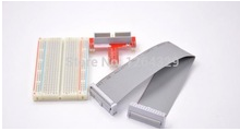
Slide 8: Connection to the Raspberry Pi
The photo shows the connections of an LED to the Raspberry Pi by
means of the cobbler (blue PCB) and a flat cable.
Like this we get access to interface pins on the Broadcom BCM2837 processor chip.
Slide 9: GPIO
GPIO or
General
Purpose
I/
O pins are pins for a single signal that
can be programmed to be input or output.
In addition internal pullup resistors can be enabled if desired.
In order to light our LED we therefore need 3 GPIO pins, one for each color.
These pins must be programmed to be output and the corresponding signal level
must be set (active high in case of common cathode, active low in case of common anode).
The intensity can be changed using pulse width modulation (pwm)
where a high frequency signal is sent to the LED.
The intensity is changed by changing the duty cycle of the signal
Slide 10: Accessing GPIOs
Of course it is possible to access the GPIOs through
register access on the processor chip.
This however is clumsy and needs detailed knowledge of the chip.
A library is available giving the programmer easy access to GPIOs,
including intensity variation through pwm.
The library we will be using is pigpio which has a Python interface.
The library uses a daemon (pigpiod), which is usually started at system startup.
It is also possible to start it manually as super user.
The Python module connects to the daemon and sends commands to it.
The daemon is responsible for the hardware access.
Please have a look at the
pigpio docs
.
Slide 11: The PIGPIO documentation

Slide 12: Accessing the LED
Before trying to access the LED by program we simply connect
- Vcc to the red, green or blue pin and GN to - in case of the common cathode PCB
- Vcc to + and GND to red, green or blue in case of the common anode PCB
This will light the corresponding color or the LED.
Then we connect the LED to the Raspberry Pi as follows:
- red to pin 18
- green to pin 17
- blue to pin 22
- - to GND in case of the common cathode version or
+ to Vcc in case of the common anode version
Slide 13: Lighting the LED by program
Strategy:
- First we import the pigpio library:
import pigpio # imports the library
- Create a pi object from the pigpio class
This will connect our program to the pigpiod daemon
pi = pigpio.pi()# connects to the daemon
- We program the gpio pins to be output:
pi.set_mode(_RED,pigpio.OUTPUT) # _RED must be set to 18
- And finally we write 0 or 1 to the pin:
pi.write(_RED,pigpio.HIGH) # or pigpio.LOW
- In order to change the intensity of the color component we use pwm:
pi.set_PWM_dutycycle(_RED, intensity) # intensity: 0..255
Slide 14: 8 Colors
if we switch each of the LEDs then, because of 3 pins, we have 8 different colors.
All pins off is black, all pins on is white.
Slide 15: Remotely connect to pigpiod
The call to pigpio can have up to 3 parameters:
pi = pigpio.pi(host,port,show_errors)
After this the program is identical to what we have seen. So
What is the difference?
In the first case both, pigpiod and the Python program run on the Raspberry Pi
and only the keyboard, mouse and screen are used to interact via the ssh interface.
In the second case the Python program runs of the PC
and only the I/O to the sensors or LEDs happen through the daemon.
Slide 16: Shades of Colors
To see 255 different shades of red, this is what we need to do:
Of course you can do the same thing for green and blue shades
or for any combination of the colors

Slide 17: Intermediate Colors, PWM
How can we get a finer definition of colors is each of the LEDs
can only be driven by binary signals?
The answer is pwm: pulse width modulation.
The signal to the LEDs is sent a a high frequency where the switching is invisible to the human eye.
The duty-cycle determines the current flowing through the LED and thus the color.
It can easily be seen that with respect to a permanent 1
a pwm signal with 50% duty-cycle produces on average only ½ of the current

Slide 18: Color and Distance Sensor
Reading the HC-SR04 ultra-sonic distance sensor and the TCS3200 color sensor
is much more complex than driving the LEDs
However, we are lucky:
There are Python classes supporting these devices written for us by experienced Python programmers.
These classes come with example code showing how to use the class methods.
Of course we can just use the code. It is however much better to try and understand the code before using it.
Reading code written by expert programmers can help us to substantially improve our own programming skills.
Slide 19: The Ultra-Sonic Distance Sensor
We can consider the sensor as a loudspeaker and microphone. These are the two cylinders.
On a trigger the sensor sends an 8 cycle burst of ultra-sound (40 kHz)
It then reads the echo and generates a pulse whose length is proportional to the signal travel time.

Slide 20: The HC-04 distance sensor

Slide 21: HC-SR04 Signal Connections
| Vcc |
5V |
| Trig |
GPIO 5 |
| Echo |
GPIO 6 via level converter |
| GND |
GND |
We create a 10 μs pulse on the Trig pin, setting gpio pin 5 to HIGH,
wait for 10 μs and setting it low again.
Then we read the time at which the Echo signal becomes high and when it becomes low again.
The time difference corresponds to the sound travel time.
Since we know that the
speed of sound in air is ~ 343 m/s
the distance the sound wave has traveled is distance = 34300/2 * signalLength [cm]
(the factor 2 comes from the fact that the wave travels from the loudspeaker
to the paper and back to the microphone, which is twice the distance)
Slide 22: Level converter
The HC-SR04 and the TCS3200 work on 5V with 5 V logic levels while
the Raspberry Pi works with 3.3V logic levels.
This is ok for Raspberry Pi output signals. The correct logic level is seen by the sensors.
However, the input signals to the Raspberry Pi must be converter to 3.3V,
which can be done with a resistor voltage divider or with a level shifter:
On the B side we provide 5V signals which are converted to 3.3V on the A side
Both sides need Vcc (side B: 5V, side A: 3.3V) and GND

Slide 23: The HC-SR04 code, init

Slide 24: The HC-SR04 code, loop

Slide 25: Timeout
There is a problem with the code:

Raspbian is a multi-tasking system, treating a large number of interrupts.
What can happen when an interrupt is treated while our program is waiting for a transition?
We may wait forever! The program gets blocked!
There are 2 ways to treat this:
- use timeouts: make sure that the time since we started waiting
for the transition does not exceed a predefined max. value
- use callbacks
Slide 26: Callbacks
We can define a Python function (the callback function) and tell pigpio to call this function
when a transition appears on a gpio pin.

Slide 27: The TCS3200 color sensor
The TCS3200 color sensor module is mounted on a GY-31 PCB.

The color sensor is based on color-light to frequency converters
where the light intensity is proportional to the frequency.
It contains an array of 8*8 photo-diodes:
16 photo-diodes have red, 16 others have green,
another 16 have blue filters and 16 have no filter.
Here is the
TC3200 data sheet
Slide 28: TCS3200 functional diagram

Slide 29: Pin-out of the GY-31 board

Vcc and GND are the power connections
LED allows to switch the while LEDs on and off (active low)
S0 & S1 are frequency scaling controls
S2 & S3 select the color component:
- 0: red
- 1: blue
- 2: clear
- 3: green
The output frequency is typically 4.5 V and must be connected to the
Raspberry Pi through a level converter transforming the signal to 3.3V
Slide 30: TCS3200 connections
This is how we connect the TCS3200 to the Raspberry Pi.
We need female to male breadboard cables to accomplish this.

Slide 31: The TCS3100 class, Initialization

Slide 32: Defining the GPIO pins

Slide 33: Setting up the Callbacks
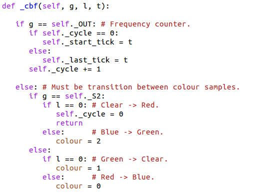
The callback routine is executed when
there is a rising edge on the OUT pin (frequency corresponding to the color intensity)
there is a change in signal level on S2 or S3 selecting the color filters
Slide 34: The Callback Function
Slide 35: Switching the LEDs on and off
Normally the 4 white LEDs on the board should be on to reflect their light on the colored paper
and measure the color components on the sensor.
Nevertheless it may be interesting to to able to switch off the LEDs once the color sensor
is not used any more.

Slide 36: Strategy to read the rgb Values
To read the rgb values we must set the color filters and then read
the out frequency for the corresponding color component. This is done for
- the red component (S2,S3 = 0,0)
- the blue component (S2,S3 = 0,1)
- and the green component (S2,S3 = 1,1)
- finally the clear component (S2,S3 = 1,0)
As you can see only a single GPIO line changes when switching filters in this sequence
Slide 37: Switching the filters

--
 Uli Raich - 2018-04-25
Comments


