The Heart Rate Sensor
Goal:
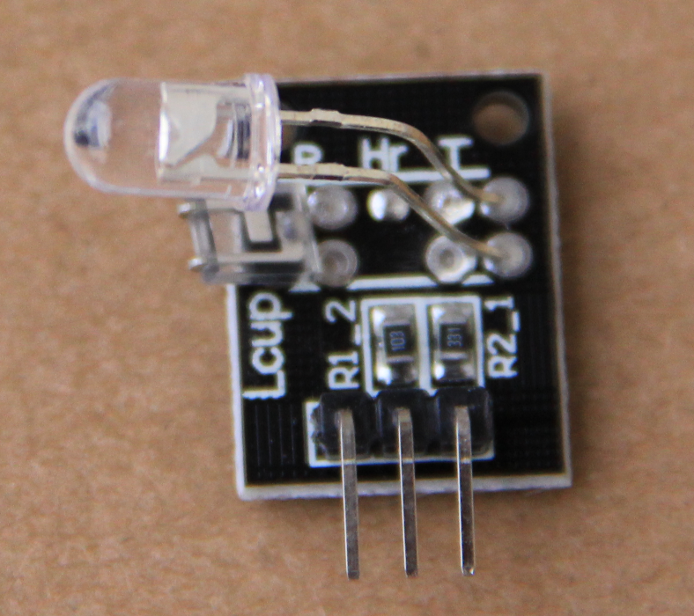
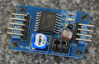
The heartbeat monitor consists of a simple Infrared LED combined with a photo diode measuring the IR light traversing you finger and arriving at the diode. When the blood is enriched with oxygen, the color of the blood becomes lighter and the diode sees more light while just before a new beat the color is darker. This results in a typical repetitive light signal which can easily be measure with an ADC.In addition to the heart beat monitor itself we us the PCF8591 ADC to read out the diode signal.  |
 |
| The Heart Rate Monitor with LED and Photo Diode |
The PCF8591 8 bit ADC |
Exercise 1: Measure the photo diode voltage when “blinking” the IR LED.
Write a program similar to the one you wrote for the LED exercises with a blink rate of 2 Hz. Then measure the voltage at the photo diode and check if you can see the blinking diode.Exercises 2: Measure the heart signal seen on the photo diode
For this to work you must hold your little finger between the LED and the photo diode. Connect the signal output from the diode to channel AIN2 of the PCF8591 ADC.
Program the ADC such that only channel C corresponding to AIN2 is selected. You may leave the jumpers on the board. They connect
- The thermistor to AIN1
- The photo resistor to AIN0
- The potentiometer to AIN3
The re-direct the output to a file and let the system run for some 20s. Finally plot the data with GnuPLot. --
Comments
| I | Attachment | History | Action | Size | Date | Who | Comment |
|---|---|---|---|---|---|---|---|
| |
blood.png | r1 | manage | 655.7 K | 2017-11-14 - 14:57 | UnknownUser | |
| |
pcf8591.png | r1 | manage | 209.7 K | 2017-11-14 - 14:57 | UnknownUser |
Ideas, requests, problems regarding TWiki? Send feedback


