
Digital to Analogue Conversion:
the mcp4275
Lecture 10
Uli Raich
UCC semester 2017/2018
Analogue versus digital
Up to now we only treated digital signals:- on/off for the LEDs
- on/off to read the LED state
- Powering or not powering coils to generate magnetic fields in a stepping motor
The world is mostly analogue:
- Temperatures are changing continuously and not in steps
- Pressure is an analogue value
- Distance, time, current, resistance are all analogue values
Converting from digital to analogue
Since our computer is a digital device we must- Convert digital values to analogue voltage levels
Digital to Analogue Conversion (DAC) -
and we must convert external analogue values to digital
Analogue to Digital Conversion (ADC)
Digital to analogue conversion
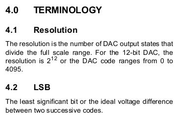
A digital to analogue converter does not really convert into a continuous waveformSince we have digital values as a base, there will be steps in the output waveform
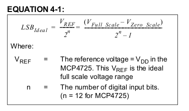
The size of these steps depends on the resolution of the DAC
What is the smallest step a 12 bit DAC can produce on a 0..5V scale?
Can we smooth the output signal?
Yes, it is possible to smooth out these steps. We need a low-pass filter, which filters out high frequencies (the abrupt steps we have in the output signal) and lets pass only slower transitions. When looking carefully at the output of our sine generator you will also see these steps. In this case however they come from the limited number of sine values (100) we calculate. To improve the resolution we would have to increase the number of samples and the frequency with which we send these values to the DAC.How does a DAC work?
 If you want to know more about DAC technology (and you should!)
have a look at this excellent tutorial
If you want to know more about DAC technology (and you should!)
have a look at this excellent tutorialThe MCP4725 12 bit DAC
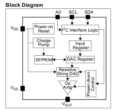
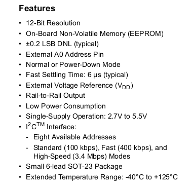
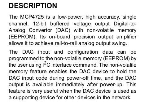
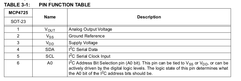
As a demo device we bought the MCP4725 DACThis is a 12 bit DAC which can be accesses by the I2C bus
Here is its data sheet

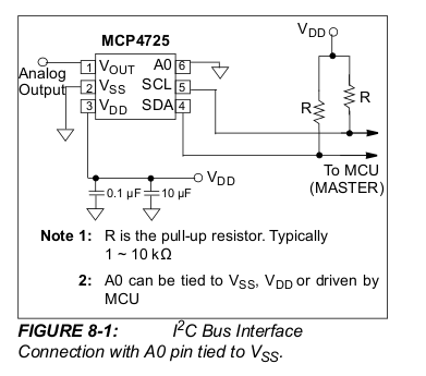
The I2C bus
The I2C bus is an industrial standard 2 wire bus using a data (SDA) and a clock (SCL) line. Adding Vcc and Gnd we need a mere 4 wires to connect a I2C device to the Raspberry Pi cobbler The I2C bus was invented by PhilipsTypical I2C connections

Open drain signals
Open drain signals mean that you can pull a line down but you cannot set it to a high level. If nobody pulls the line down, then it is at Vcc level, pulled up by a pull-up register. Like this the contention problem is solved where one device tries to set a line to a high level, while another sets it to low, thus creating a short circuit.I2C Master and slave
The I2C bus has at least one master (in our case the interface in the Raspberry Pis ARM processor) and several slaves We have the following I2C slave devices:- mcp4275 DAC
- bmp180 barometric pressure sensor
- pcf8581 8 bit ADC
- ads115 16 bit ADC
- at24c32 eeprom
- ds1307 real time clock
- mma845x accelerometer
- pcf8574 I/O expander used on the 2-line LCD display
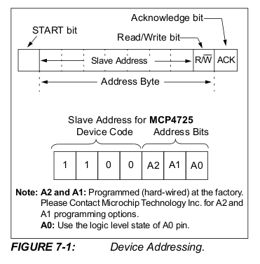
I2C addressing
Since there can be several slaves on the bus there must be a means of distinguishing them through addressing: Every I2C slave has a 7 bit address associated with it Usually this address is determined by the manufacturer but often there are address pins on the devices allowing the user to have several devices of the same type on the busI2C buses and I2C addresses on the Raspberry Pi
The Raspberry Pi has 2 I2C buses with bus 1 being put onto the cobbler You can find out the addresses of the I2C slaves are currently connected with the i2cdetect command
Initiating a I2C transfer

Start stop conditions
The master starts a transfer by creating a start condition:- high to low transition on SDA while SCL is high
- stop condition: low to high transition on SDA while SCL is high4

Data transmission
Data are transmitted with the SDA line stable with SCL is high
A write cycle
A write cycle:After the start condition the device address. The eighth bit, the R/W bit is kept low.
The second data byte is considered the register byte and the last one the data byte
The slave acknowledges each byte transfer.

The read cycle
The read cycle is a bit more complex: First the master sends the slave address with R/W set to write Then it sends the register information. After that another address byte is sent, this time with RW set to read And finally the slave sends the data. The master still sends the clock but releases the SDA line allowing the slave to control it --
-- Comments


| I | Attachment | History | Action | Size | Date | Who | Comment |
|---|---|---|---|---|---|---|---|
| |
INL_Def.png | r1 | manage | 28.9 K | 2017-10-31 - 18:03 | UnknownUser | |
| |
addressing.png | r1 | manage | 31.1 K | 2017-10-31 - 18:03 | UnknownUser | |
| |
blockDiagram.png | r1 | manage | 26.2 K | 2017-10-31 - 18:03 | UnknownUser | |
| |
connection.png | r1 | manage | 30.9 K | 2017-10-31 - 18:03 | UnknownUser | |
| |
dacPrinc.png | r1 | manage | 39.1 K | 2017-11-01 - 08:57 | UnknownUser | |
| |
dacSpecs.png | r1 | manage | 33.9 K | 2017-10-31 - 18:03 | UnknownUser | |
| |
dac_front.png | r1 | manage | 1097.6 K | 2017-10-31 - 18:03 | UnknownUser | |
| |
dataTransfer.png | r1 | manage | 18.7 K | 2017-11-03 - 16:50 | UnknownUser | |
| |
eqation.png | r1 | manage | 17.0 K | 2017-10-31 - 18:03 | UnknownUser | |
| |
i2c_conn.png | r1 | manage | 23.8 K | 2017-11-03 - 16:26 | UnknownUser | |
| |
i2cdetect.png | r1 | manage | 25.5 K | 2017-11-03 - 16:44 | UnknownUser | |
| |
initiate.png | r1 | manage | 19.2 K | 2017-11-03 - 16:49 | UnknownUser | |
| |
inlDiag.png | r1 | manage | 24.6 K | 2017-10-31 - 18:03 | UnknownUser | |
| |
mcp4725Desc.png | r1 | manage | 38.5 K | 2017-10-31 - 18:03 | UnknownUser | |
| |
pinout.png | r1 | manage | 33.6 K | 2017-10-31 - 18:03 | UnknownUser | |
| |
readCycle.png | r1 | manage | 12.7 K | 2017-11-03 - 16:49 | UnknownUser | |
| |
resolution.png | r1 | manage | 17.6 K | 2017-10-31 - 18:03 | UnknownUser | |
| |
settlingHigh.png | r1 | manage | 31.5 K | 2017-10-31 - 18:03 | UnknownUser | |
| |
settlingLow.png | r1 | manage | 30.4 K | 2017-10-31 - 18:03 | UnknownUser | |
| |
settlingTime.png | r1 | manage | 16.9 K | 2017-10-31 - 18:03 | UnknownUser | |
| |
startStop.png | r1 | manage | 7.8 K | 2017-11-03 - 16:50 | UnknownUser | |
| |
writeCycle.png | r1 | manage | 11.8 K | 2017-11-03 - 16:49 | UnknownUser |

|
|
|
|
Ideas, requests, problems regarding TWiki? Send feedback