Slide 1: Stepping Motors
Lecture 8
Uli Raich
UCC semester 2017/2018
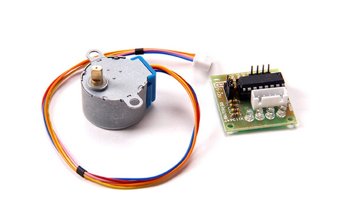
Slide 2: The 27BJY-48 stepper motor an its ULN-2803 driver module

Slide 3: Stepping Motors versus DC Motors
While DC motors simply spin when they are powered,
stepping motors can be moved in defined steps and thus positioned very precisely.
They contain 2 coils which can be powered in positive or negative
direction making the current flow in normal or reverse direction
and thus creating magnetic fields of opposite polarity
The rotor has a series of magnets (16 in case of the 28BYJ-48 which we are using)
with alternating opposite polarization.
A north pole followed by a south pole followed by a north pole and so on.
The motor base has 2*16 teeth which can be polarized as
north or south poles depending on the direction of the coil current.
Here is the data sheet of the
28BYJ-48
Slide 4: The Driver Card
The maximum current that a GPIO pin on the Raspberry Pi can deliver is 60 mA
which is insufficient to power the motor coils.
We therefore need a driver circuit (Darlington stage) to amplify
this current. In our case we use the
ULN-2803
chip
The little PCB has 4 LEDs on it to show which of the 2 coils is
powered and in which direction. This is very useful to demonstrate which signals
are sent to the motor and it illustrates nicely the functioning of the motor.
Slide 5: Connecting the Driver to the Motor

We can see from the connections that when powering the pink line
the coil current is flowing in one direction while when
powering the orange line it is flowing in the opposite direction
Slide 6: Motor Movement
First we power the first coil in such a way the the first tooth has a
south pole and the second one a north pole, which
makes the rotor (whose north magnet is considered) moves to the first tooth.
Then we switch off the first coil and power the second coil such that
the first tooth of the lower row has a south pole.
This makes the rotor move to this tooth.
Now switch off the second coil and switch the first one on again,
however this time with reverse current. The second tooth of the
upper row now has the south pole
(the poles are inversed with respect to the first step).
Now we switch on only the second coil with inverse current to make
the rotor move to the forth tooth. From now on the whole cycle repeats.
--
 Uli Raich - 2017-10-16
Comments


 We can see from the connections that when powering the pink line
the coil current is flowing in one direction while when
powering the orange line it is flowing in the opposite direction


