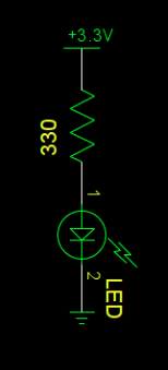
LEDs
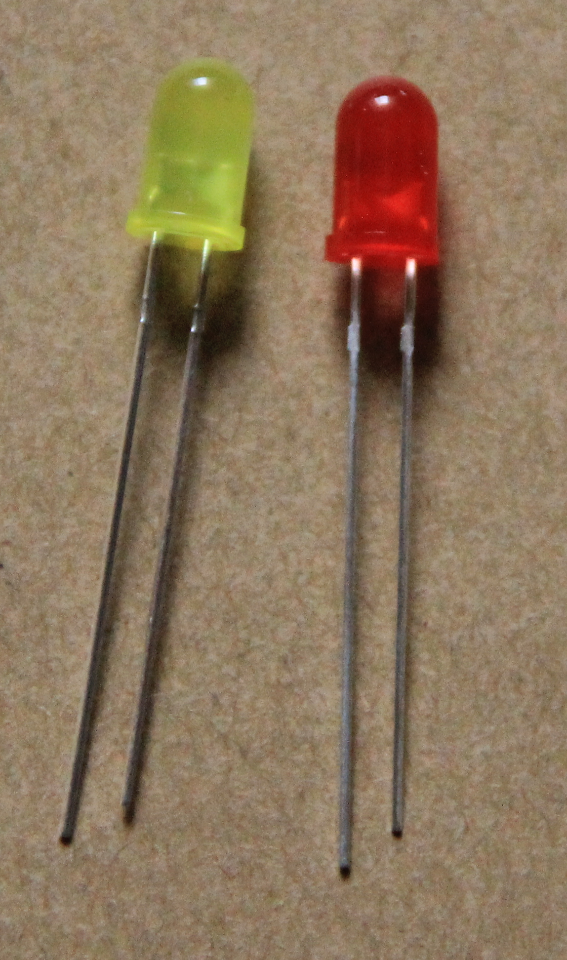
5 out of the 37 sensors are some sort of LEDS: First we have the standard LEDs (not part of the sensor kit)  |
 |
|
2 colored LEDs
The sensor kit has 5 LED circuits which feature multi-color LEDs. First there are 2 color LEDs with exactly the same functionality but different LED sizes. 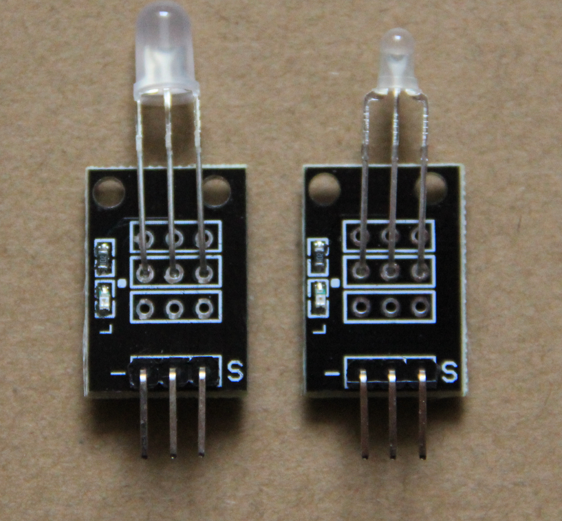 |
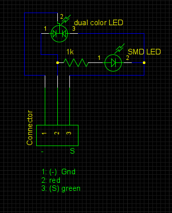 |
through pin 2 (+) and pin 3 (S, now “-”, note that S is the “+” pin when accessing the 2-colored LED)
rgb LEDs
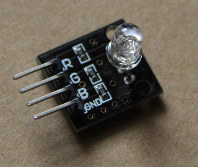
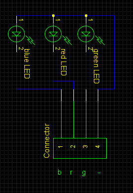
Again we have 2 circuit boards with essentially the same functionality. 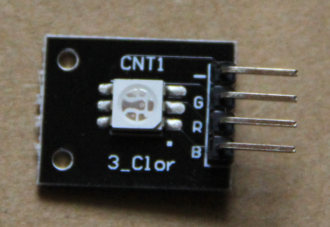 |
 |
 |
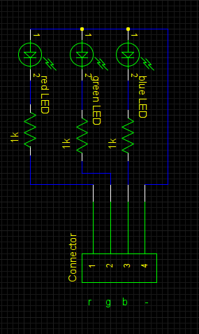 |
So … be careful!
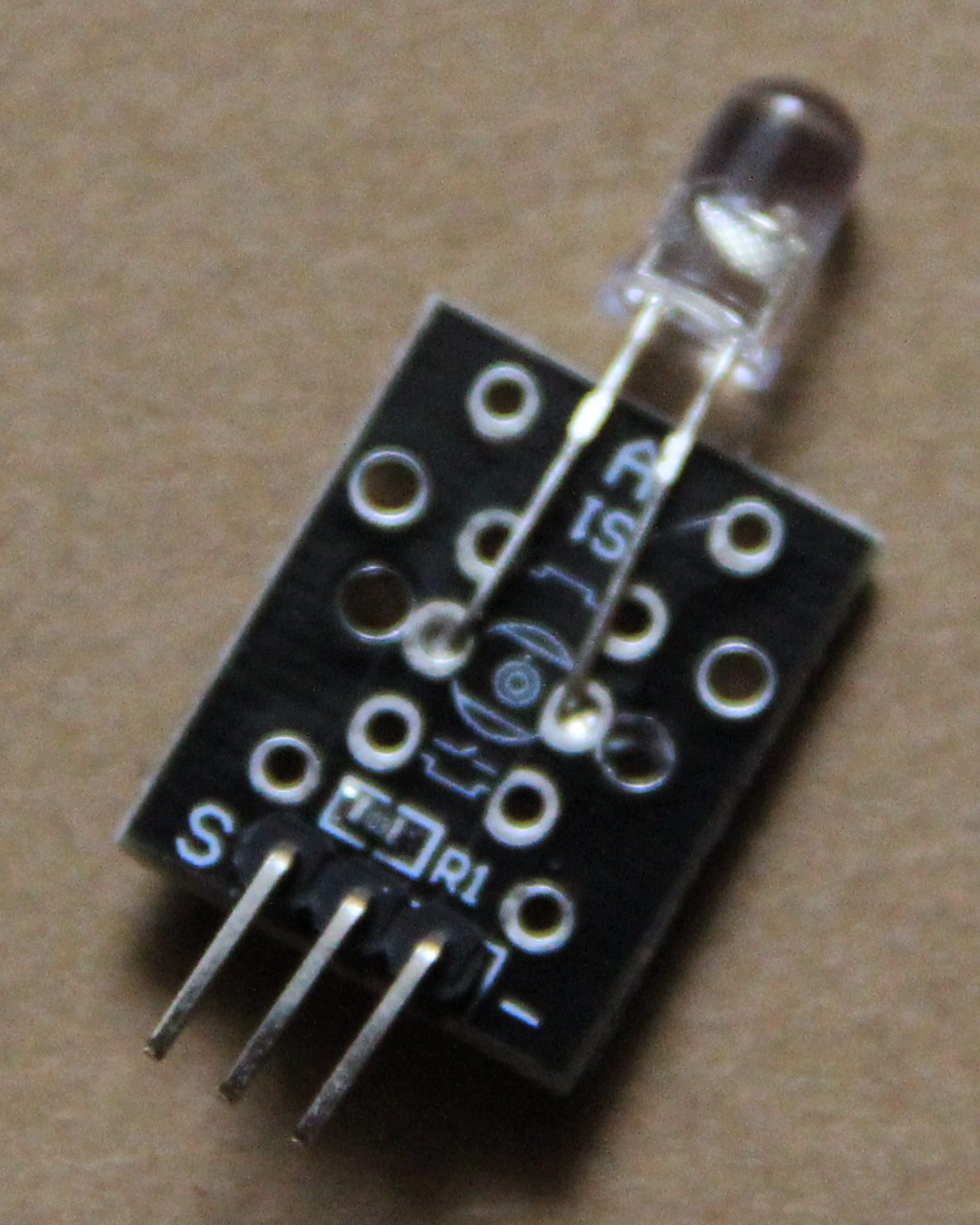
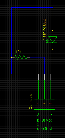
The flashing colored LED
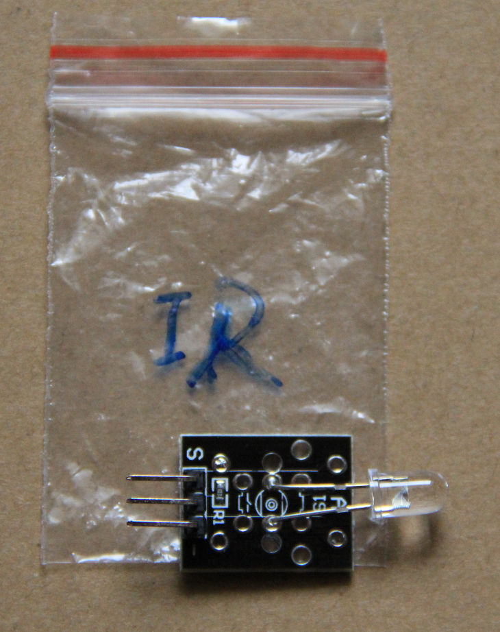
This LED automatically cycles through different colors and flashes. It is connected like the simple LED. In addition to the flashing colored LED there is the IR (infra red)transmitter which is hardly distinguishable from the flashing LED. The plastic bag containing the PCB however is clearly marked.
 |
 |
Not to be confused with this ->
|
 |
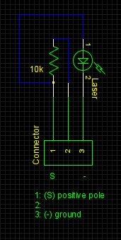
The Laser
In contrast to the LEDs the laser can be directly connected to 3.3V. 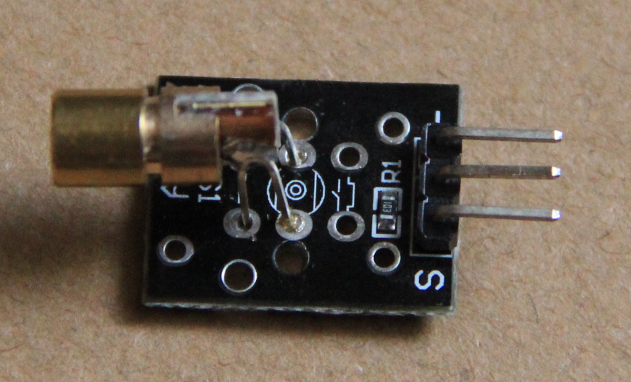 |
 |
Comments
| I | Attachment | History | Action | Size | Date | Who | Comment |
|---|---|---|---|---|---|---|---|
| |
2colLedschematic.png | r1 | manage | 11.4 K | 2017-01-03 - 20:24 | UnknownUser | 2 colored LED schematic |
| |
2colorLEDs.png | r1 | manage | 980.4 K | 2017-01-03 - 20:45 | UnknownUser | 2 colored LEDs |
| |
3colLed-1.png | r1 | manage | 495.1 K | 2017-01-03 - 20:52 | UnknownUser | SMD rgb LED |
| |
3colLed-2.png | r1 | manage | 581.9 K | 2017-01-03 - 20:52 | UnknownUser | rdb LED |
| |
IREmit.png | r1 | manage | 1104.6 K | 2017-01-03 - 21:02 | UnknownUser | IR transmitter |
| |
flashSchematic.png | r1 | manage | 6.9 K | 2017-01-03 - 20:24 | UnknownUser | flash LED schematic |
| |
flashingLED.png | r1 | manage | 2292.9 K | 2017-01-03 - 21:03 | UnknownUser | flash LED |
| |
laser.png | r1 | manage | 414.1 K | 2017-01-03 - 21:02 | UnknownUser | laser |
| |
laserSchematic.png | r1 | manage | 6.7 K | 2017-01-03 - 21:09 | UnknownUser | laser schematic |
| |
led.png | r1 | manage | 51.1 K | 2017-01-03 - 20:28 | UnknownUser | LED explanation |
| |
leds.png | r1 | manage | 2950.7 K | 2017-01-03 - 20:10 | UnknownUser | standard LEDs |
| |
ledschematics.png | r1 | manage | 7.2 K | 2017-01-03 - 20:28 | UnknownUser | LED schematics |
| |
rgbSMDschematic.png | r1 | manage | 7.6 K | 2017-01-03 - 20:24 | UnknownUser | SMD rgb LED schematic |
| |
rgdLEDschematic.png | r1 | manage | 9.8 K | 2017-01-03 - 20:25 | UnknownUser | rgb LED schematic |
Ideas, requests, problems regarding TWiki? Send feedback
