Stepping Motor Exercises
Goal:
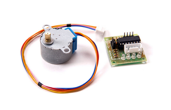
A stepping motor is a device which is often used when a precise amount of movement is required: an exact angle of a an exact position on a linear scale. While DC motors move while they a powered a stepping motor requires a sequence of impulses to move step by step as its name suggests. In this exercise we will learn how to program different step sequences for full step of half step movement and how to move the motor forward and backward. This is a photo of the motor itself and its driver module featuring an ULN2803 driver chip.
Exercise 1: Make sure the connections are correct
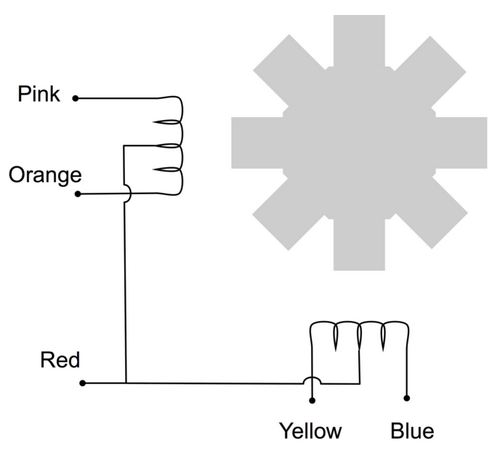
The stepping motor is has 5 connections which are provided by the cable from the driver module to the motor itself. The 2 coils must be energized in the right order. To do this we have 6 connections from the driver board to the Raspberry Pi:
 -
5V (check for “5V +” and “-” on the board)
-
Gnd
-
4 phases denominated In0..In3
- phase 1 on pin 27
- phase 2 on pin 22
- phase 3 on pin 18
- phase 4 on pin 17
Exercise 2: Write a program to move the stepping motor by 2048 steps.
Use the single phase sequence to make the stepping motor move. One sequence corresponds to 4 full steps. Make sure to wait at least 25 ms in between each setting:-
set 1 0 0 0, wait 25ms
-
set 0 1 0 0, wait 25 ms …
Exercise 3: Modify the stepping tables
Modify the tables with the values for In0..In3 to use single phase stepping, double phase stepping and half step mode. How do you have to modify these tables if you want the motor to turn the other direction? Try all 6 combinations:- single phase forward
- single phase backward
- double phase forward
- double phase backward
- half step forward
- half step backward
Exercise 4: Improve your program to give user control over its parameters
Modify your program in such a way that the user can define its behavior through command line parameters:-
-f or –forward: move forward (this is the default)
-
-b or –backward: move backward
-
-n or –numberOfSteps: number of steps (default 512)
-
-v or –velocity: velocity of movement
-
-s or –fullStep: full step (this is the default)
-
-h or –halfStep: half step
Additional Exercises:
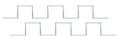
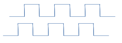
The "inverse device" to the stepping motor is a rotary encoder. Here we do not send the pulse sequence to move a motor but we receive the sequence to be able to tell by how far the motor has moved. The encoder is usually fixed to the motor shaft and it tells us the angle or position of the motor. Reading out an encoder is not really part of this exercise but since we have such an encoder in our sensor kit I played on it and I give you some code to read out the encoder in the solutions section to this exercise. The following signal shapes show the encoder signals when moving clockwise and counter clockwise
 --
-- Comments
--
Comments
| I | Attachment | History | Action | Size | Date | Who | Comment |
|---|---|---|---|---|---|---|---|
| |
clockwise.png | r1 | manage | 2.9 K | 2017-10-26 - 12:04 | UnknownUser | |
| |
counterClockwise.png | r1 | manage | 2.9 K | 2017-10-26 - 12:04 | UnknownUser | |
| |
stepping.pdf | r1 | manage | 310.0 K | 2017-11-27 - 10:34 | UnknownUser | |
| |
stepping.png | r1 | manage | 182.9 K | 2017-05-11 - 12:22 | UnknownUser | |
| |
steppingMotor.odt | r1 | manage | 231.1 K | 2017-10-25 - 18:55 | UnknownUser | |
| |
windings.png | r1 | manage | 28.7 K | 2017-05-11 - 12:22 | UnknownUser |
Ideas, requests, problems regarding TWiki? Send feedback


