Seven Segment Display and Keypad
The Seven Segment Display and its TM1637 controller
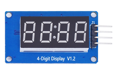
There is a nice and simple seven segment display controlled by a TM1637 controller, which can be used e.g. as a clock display. It provides 4 digits and a colon dividing digits 1 and 2 from digits 3 and 4, such that the first two digits can be used to display hours, the last two digits to display minutes and the colon can be set blinking at a 1 Hz rate. Of course you can also use it for other purposes like displaying the voltage values of a voltmeter.
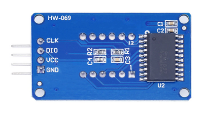
As can be seen from the back view of the module, interfacing to the ESP32 is pretty simple. Here are the connections I use:
The data sheet for the TM1637 controller can be found at
https://www.mcielectronics.cl/website_MCI/static/documents/Datasheet_TM1637.pdf
.
The TM1637 uses a proprietary 2-wire serial protocol with a data line (dio) and a clock line.
Exercise 1:
Carefully read the data sheet.
Write a driver implementing the serial protocol. Implement the driver as class
TM1637 with the following methods:
- start_transfer: implements the start sequence (dio going low when clk is high)
- stop transfer: implements the "end of transfer" sequence (dio going high when clk is high)
- write_bit: write a single bit: with clk low, set dio to the bit value, then send a pulse (high followed by low) on the clk pin
- write byte: send 8 bits. After the eights bit, check the acknowledge signal. Switch dio to input, check acq, switch dio back to output after the falling edge of the nineth clock pulse
- display on: switch the display on: start_transfer, send display_on command, stop transfer
- create a table with the led setting of the seven segments for all hex digits and a clear digit (all segments off). dp means decimal point, which is only used on the second digit, where it controls the following colon.
      A
     ---
  F |   | B      dp,g,f,e, d,c,b,a: the data byte
     -G-
  E |   | C
     ---
      D
- write_digit(digit_num,digit,colon=False): sets digit number digit_num to the value digit. If colon is true and the digit number is 1 (start counting from zero) the switch the colon on.
- clear_digits(colon=False): clear all digits. Only the colon stays on if colon == True
- write_hex(number,colon=False): write a hex number to the display
- write_dec(number,colon=False): write a decimal number to the display.
Write a test routine that exercises all the above methods
Exercise 2:
Read the current time from the ntp and implement a clock displaying hours and minutes. Make the colon blink at a 1 Hz rate.
The Keypad
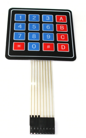
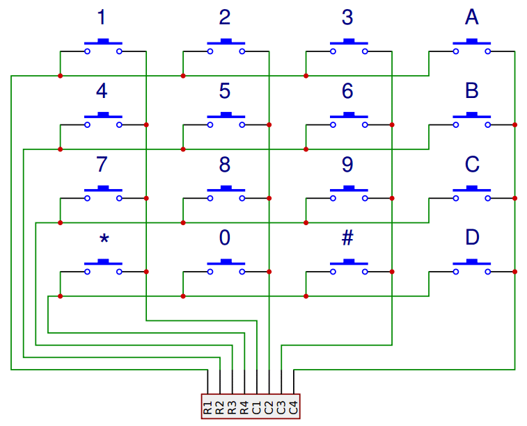
The keypad has a total of 16 switches. These are connected to 8 pins organized as 4 rows and 4 columns.
The job will be to find out which row makes a connection to which column in order to find out which switch is closed. This can be done by connecting e.g. the 4 row pins to GPIO outputs and the 4 column pins to GPIO inputs with pull-ups.
Set the first row pin to low and check on each column pin if you read a zero. If you do, you have found the switch closed. If not, continue the same procedure on the other row pins.
I made the connections as follows:
| Row 1 |
D7: GPIO 23 |
| Row 2 |
D6: GPIO 19 |
| Row 3 |
D5: GPIO 18 |
| Row 4 |
D0: GPIO 26 |
| Col 1 |
D4: GPIO 16 on WROVER: GPIO 25 with patch to D4 on CPU board |
| Col 2 |
D3: GPIO 17 on WROVER: GPIO 4 with patch to D3 on CPU board |
| Col 3 |
D2: GPIO 21 |
| Col 4 |
D1: GPIO 22 |
Exercise 1:
Scan the keyboard in intervals of 100 ms and print the key that is pressed. This will result in printing the key as long as it is pressed.
Exercise 2:
Wait until the key is released and only then print the key. This will result in a single key value for each button press.
Exercise 3:
Write a
CircularBuffer class in which you can keep key presses. This will allow to read the keypad completely asynchronously (see exercise 4).
The
CircularBuffer class should implement a buffer of 32 elements with the following methods:
- write: add an element to the end of the buffer. Check if the buffer is full before writing and set the overrun flag if this is the case
- available: check if new data have arrived in the buffer
- read: read data from the buffer if it is not empty
- is_full: tells if the buffer is full
- overrun: tells if an overrun error has occurred in the past
- clr_overrun: clear the overrun flag
- flush: clears the buffer
Write a test script exercising the
CircularBuffer class.
Exercise 4:
Read the keypad in an interrupt driven routine. Keep the pressed keys in the circular buffer written in exercise 3.
Write a test program that starts the interrupt driven keypad driver and reads data from the circular buffer in rather large intervals (e.g. every 5s or 10s)


