| |
| META TOPICPARENT |
name="LectureSlides" |

Slide 1: Stepping Motors |
| | Now we switch on only the second coil with inverse current to make
the rotor move to the forth tooth. From now on the whole cycle repeats.
|
|
<
< |
|
>
> |
|
| | |
|
>
> | Signal Table for Single Phase Forward
We have seen in the last slide how we have to power the coils to
make the stepping motor move by 1 cycle, which is 4 steps in case of
Single Phase Forward stepping
How does this translate into a program?
We connect the 4 phases (coil 1 forward, coil 2 backward, coil 1 backward, coil 2 forward)
to 4 GPIO pins on the Raspberry Pi cobbler
Then we create the following signal table, which is a 2-dimensional array of booleans:
| |
|
Step 1 |
Step 2 |
Step 3 |
Step 4 |
| In 1 |
coil 1 + |
1 |
0 |
0 |
0 |
| In 2 |
coil 2 - |
0 |
1 |
0 |
0 |
| In 3 |
coil 1 - |
0 |
0 |
1 |
0 |
| In 4 |
coil 2 + |
0 |
0 |
0 |
1 |
Sending the pulses to the hardware
Now all we have to do is to go through this table and, for each step,
send a high level to the GPIO pin to which we connected the coils.
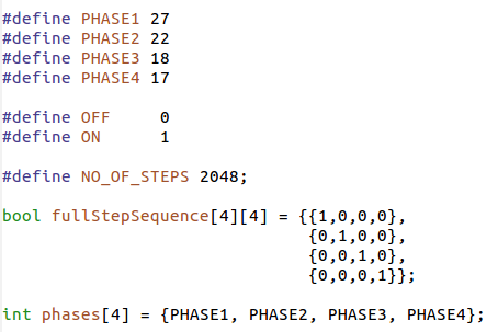
Going through one step cycle
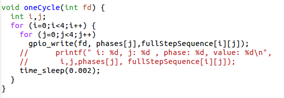
Other modes of operation
Single Step forward (and backward) works fine but we can do better.
Up to now we have always powered only one coil at a time.
It is however possible to power both coils at the same time.
This will draw of course more current but the motor will get
a higher torque and can therefore handle bigger loads. |
| |
|
|
>
> |
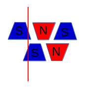
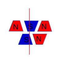
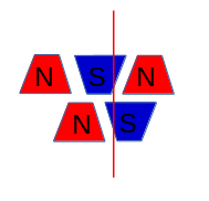
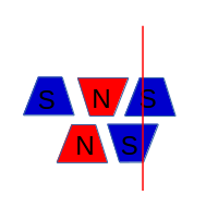
Position of rotor in doubleStepForward mode
An important point to note is that the rotor moves half a step
further than in single StepForward because its north pole
is now attracted by the top and the bottom south poles.
By first powering only the upper coil, then powering both coils
then powering again only one pole of the lower coil it should
be possible to move the motor by half steps only
and by doing so increase its resolution.
This is what we call half step mode and it is a combination
of single and double step forward modes.
The torque of the motor is less than in double step forward
and the speed is only about half because now we need 8 steps for a full cycle. |
| |
%SLIDESHOWEND% |
| |
| META FILEATTACHMENT |
attachment="step3.png" attr="" comment="" date="1508161292" name="step3.png" path="step3.png" size="4864" user="uli" version="1" |
| META FILEATTACHMENT |
attachment="step4.png" attr="" comment="" date="1508161292" name="step4.png" path="step4.png" size="4757" user="uli" version="1" |
| META FILEATTACHMENT |
attachment="connections.png" attr="" comment="" date="1508162286" name="connections.png" path="connections.png" size="30612" user="uli" version="1" |
|
|
>
> |
| META FILEATTACHMENT |
attachment="doubleStep1.png" attr="" comment="" date="1508232004" name="doubleStep1.png" path="doubleStep1.png" size="5443" user="uli" version="1" |
| META FILEATTACHMENT |
attachment="doubleStep2.png" attr="" comment="" date="1508232004" name="doubleStep2.png" path="doubleStep2.png" size="5766" user="uli" version="1" |
| META FILEATTACHMENT |
attachment="doubleStep3.png" attr="" comment="" date="1508232004" name="doubleStep3.png" path="doubleStep3.png" size="5304" user="uli" version="1" |
| META FILEATTACHMENT |
attachment="doubleStep4.png" attr="" comment="" date="1508232004" name="doubleStep4.png" path="doubleStep4.png" size="5591" user="uli" version="1" |
| META FILEATTACHMENT |
attachment="stepTable.png" attr="" comment="" date="1508232026" name="stepTable.png" path="stepTable.png" size="18780" user="uli" version="1" |
| META FILEATTACHMENT |
attachment="oneCycle.png" attr="" comment="" date="1508232026" name="oneCycle.png" path="oneCycle.png" size="19040" user="uli" version="1" |
|


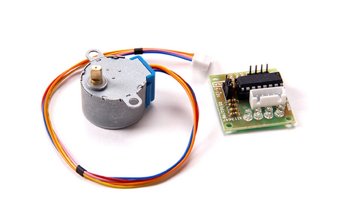
 We can see from the connections that when powering the pink line
the coil current is flowing in one direction while when
powering the orange line it is flowing in the opposite direction


