Devices needed
The Raspberry Pi
The Raspberry Pi features- SoC: Broadcom BCM2837
- CPU: Quad Core ARM Cortex-A53, 1.2 GHz
- RAM: 1GB LPDDR2 (900 MHz)
- Networking: 10/100 Ethernet, 2.4 GHz 802.11n WiFi
- Storage: micro SD
- Ports: HDMI, 4*USB2.0, Ethernet, Camera, Serial Interface, Display Interface
 It is better to use a plastic case for protection:
 In addition to the processor board itself we need a 5V, 2.5 A power supply with micro USB connector
 and a micro SD card for storage. This card will hold the operating system and all the user and system files.
 In order to access external devices like our sensors a series of interfaces are available:
 - general purpose I/O pins (GPIO)
- standard tx,rx serial interface
- I2C instrumentation bus
- SPI interface
 Now, all we need in addition are the sensors themselves and some connecting cables:
 The HC-SR04 ultra-sonic distance sensor
 |
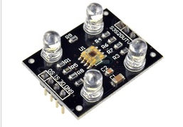
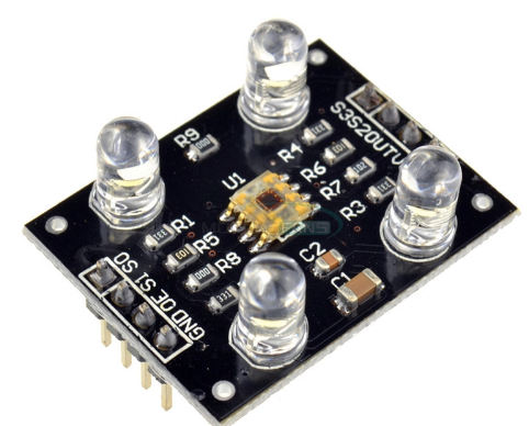 The TCS3200 colour sensor
 |
|
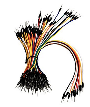
male-male bread board wires |
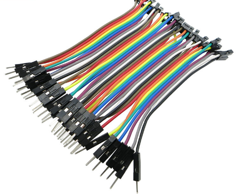
male-female bread board wires |
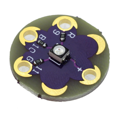
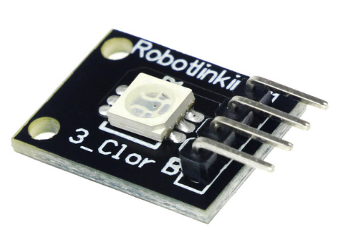
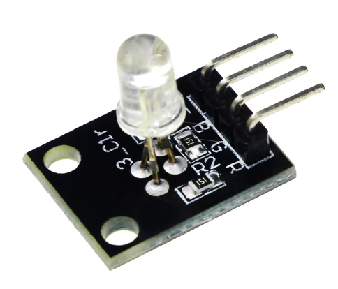 RGB LED with current limiting resistors.
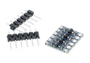
Since the Raspberry Pi GPIOs all work on 3.3V, the HC-SR04 as well as the TCS3200 however work with TTL (5V) logic, we need a level converter to bring down the sensor signal levels from 5V to 3.3V. This can be done either with a voltage divider using 2 resistors or with this level converter
RGB LED with current limiting resistors.
Since the Raspberry Pi GPIOs all work on 3.3V, the HC-SR04 as well as the TCS3200 however work with TTL (5V) logic, we need a level converter to bring down the sensor signal levels from 5V to 3.3V. This can be done either with a voltage divider using 2 resistors or with this level converter
 --
-- Comments


| I | Attachment | History | Action | Size | Date | Who | Comment |
|---|---|---|---|---|---|---|---|
| |
case.png | r1 | manage | 42.1 K | 2018-01-21 - 16:21 | TWikiAdminUser | |
| |
cobbler.png | r1 | manage | 42.4 K | 2018-01-21 - 16:21 | TWikiAdminUser | |
| |
colorSensor.png | r1 | manage | 50.0 K | 2018-01-21 - 16:15 | TWikiAdminUser | |
| |
fm-wires.png | r1 | manage | 196.1 K | 2018-02-08 - 12:08 | UliRaich | |
| |
hc-sr04.png | r1 | manage | 50.9 K | 2018-01-21 - 16:15 | TWikiAdminUser | |
| |
levelConverter.png | r1 | manage | 55.9 K | 2018-02-08 - 11:50 | UliRaich | |
| |
lilyPad.png | r1 | manage | 152.8 K | 2018-03-06 - 13:13 | UliRaich | |
| |
powerSupply.png | r1 | manage | 28.8 K | 2018-01-21 - 16:21 | TWikiAdminUser | |
| |
raspberry.png | r1 | manage | 229.6 K | 2018-01-21 - 16:15 | TWikiAdminUser | |
| |
rgbLED-1.png | r1 | manage | 128.6 K | 2018-03-06 - 13:13 | UliRaich | |
| |
rgbLED.png | r1 | manage | 153.9 K | 2018-02-08 - 11:50 | UliRaich | |
| |
rgbLED_smd.png | r1 | manage | 144.1 K | 2018-03-06 - 13:13 | UliRaich | |
| |
sd.png | r1 | manage | 10.3 K | 2018-01-21 - 16:21 | TWikiAdminUser | |
| |
tcs3200.png | r2 r1 | manage | 199.3 K | 2018-03-06 - 13:13 | UliRaich | |
| |
wires.png | r1 | manage | 109.3 K | 2018-01-21 - 16:21 | TWikiAdminUser |

Ideas, requests, problems regarding TWiki? Send feedback