Using the Atmel AVR Arduino as IoT node
Introduction
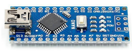
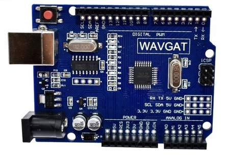
Together with the Raspberry Pi the Arduino is one of the most popular platform in embedded systems. The family of Arduino boards is quite large with the Nano, Uno and Mega being the most used ones. The boards are very cheap (<2 US$ for a Nano, <3 US$ for the Uno and 7-8 US$ for a Mega. These were the cheapest prices I found in China)
The Arduino Uno and the Arduino Mega come with a standardized pin-out for which several piggy back "shields" are available that can simply be stacked on the processor board.
 |
 |
| Arduino Nano |
Arduino Uno |
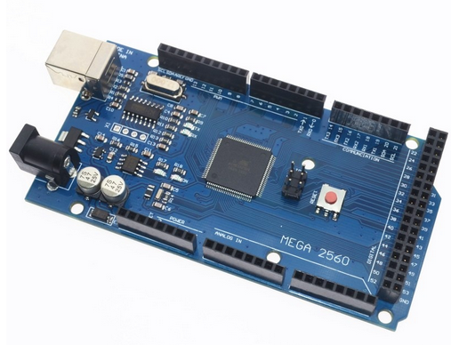 |
| Arduino Mega |
The Arduino features an
Software
Development
Kit, the
Arduino SDK
or Arduino IDE (
Integrated
Development
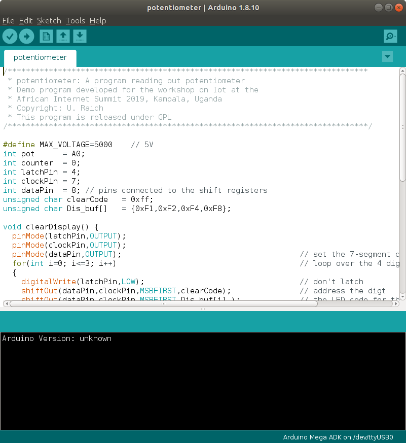
Environment), which makes software development in a C++ like language as well as flashing the binary very easy. A particular advantage of the Arduino is the large number of libraries. For almost every sensor or actuator on the market you will find a library easing considerably the development of IoT software. Libraries for network access, MQTT and Cayenne are also available.
Another advantage is the built-in 10 bit ADC making it easy to read put analog signal levels.
Problems when using the AVR Arduino are the missing network interface which must be added as a shield and, at least for the Nano and the Uno, its very limited resources in RAM space (2 kBytes only).
The network interface
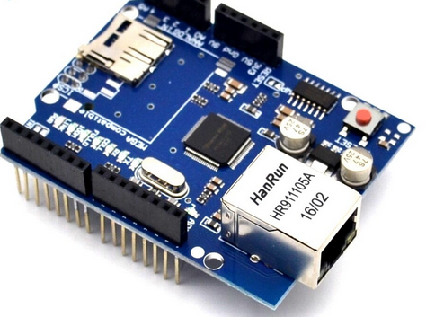
When trying to use the Arduino as an IoT node on Cayenne for the first time, I used the Arduino Ethernet shield as network interface. This worked without problems and the code generated in Cayenne worked out of the box. However, when trying to use the board during a workshop in a hotel there is a fair chance that only WiFi will be available for network access.
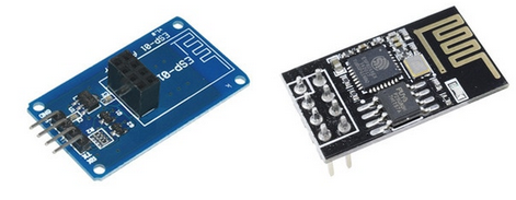
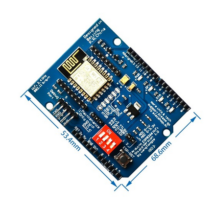
I therefore looked for a WiFi interface for the Arduino and found these two:
In my collection of Arduino shields I have a multi-function board with
- 3 user push button switches
- 4 user LEDs
- a 4 digit 7-segment display
- a passive buzzer
- a potentiometer connected to the Arduino ADC
and you can optionally connect
- an LM35 analog temperature sensor
- a DS18B20 digital temperature sensor
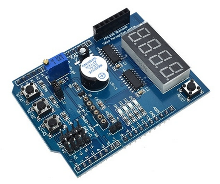
I therefore decided to try getting this board connected on an Arduino Mega acting as an IoT node and communicating through Cayenne.
A warning: If you are not willing to put a major effort into getting the WiFi shield to work then do not buy it!
The WiFi interface
Both WiFi modules are based on the ESP8266 processor chip which has a WiFi interface integrated into its silicon and which communicates with its host processor through AT commands over a serial line. Many versions of the AT firmware are floating around on the net but you can probably do with the version pre-installed. A list of available AT commands can be found
here
.
The Arduino Uno or Mega are running on 5V while the WiFi module needs 3.3V, which means that we need a level converter. This is accomplished with the blue module seen on the left on the photo together with the ESP01. On the WiFi shield the level converter is implemented on the board. There are also several versions of the WiFi shield available on the market having different misspellings on them. On the one I bought the word "More" is misspelled to "Moer" and this series has wrong transistors installed on their level converters which must be replaced to make the converter work. Here is a
detailed description
.
Another problem with the WiFi is the fact that the communication between the CPU card and the shield uses Tx0 and Rx0, which are also used upload and flashing and for the debug monitor. In order to upload code to the Arduino flash the connection to the WiFi shield must therefore be cut. This is done with the 2 left most switches on the 4 dip switch block (switch set to off position). Unfortunately you do not have access to these switches if the multi-function board is plugged on top of the WiFi shield.
I therefore used the ESP01 with its level converter connected to Tx0 and Rx0 and powered with a separate 3.3V power supply. When flashing new code I have to switch this power supply off and therefore disable the ESP01. The power is switched back on once flashing has finished.
The C++ code connecting the multi-function board to Cayenne
The code controlling the devices on the multi-function board as well as the programs making the devices visible on Cayenne can be found on
https://github.com/uraich/multifunctionCayenne
--
 Uli Raich - 2019-05-10
Comments


 Problems when using the AVR Arduino are the missing network interface which must be added as a shield and, at least for the Nano and the Uno, its very limited resources in RAM space (2 kBytes only).
 I therefore looked for a WiFi interface for the Arduino and found these two:
 I therefore decided to try getting this board connected on an Arduino Mega acting as an IoT node and communicating through Cayenne.
A warning: If you are not willing to put a major effort into getting the WiFi shield to work then do not buy it!


