
Slide 1: An additional Lecture on C Programming
Creating a Signal Generator
Uli Raich
Course on Embedded Systems
UCC semester end 2017
Slide 2: C is too abstract?
I was told that you find the course on C too abstract!- What is is good for?
- What are pointers good for?
- Why use command line arguments?
- What has all this to do with embedded systems?
- Can I use it for my Physics experiments?
Slide 3: A pulse generator
A pulse generator is a device you use to test your electronics (e.g. electronics to read out an experiment which generates electronic signalsOn a professional pulse generator you can:
- change the wave form
sine, rectangular, triangular, sawtooth,
arbitrary user defined wave form - change the frequency
- change the pulse height
- change rise and fall times
- and many parameters more
Slide 4: The oscilloscope
Before using the signal from the pulse generator you observe the signal on an oscilloscope How does an oscilloscope work? What is- vertical gain
- time base
- auto versus normal, external, single trigger
- trigger level and trigger position
Slide 5: A standard oscilloscope
A standard digital storage oscilloscope uses- a very fast (GHz) analogue to digital converter (ADC)
- plenty of knobs and buttons to select
gain, timebase, trigger parameters - a screen to display the input signal
- Price: ~ 5kUS$ - 50kUS$
- 2 input channels
- 40 MHz sampling rate (20 MHz band width)
- No screen
- USB connection to a computer
Slide 6: Oscilloscope Example

Slide 7: Our pulse generator
Let us create our own pulse generator!It should provide
- sine wave
- rectangular wave
- A table of numerical values that describes the wave form
- A digital to analogue converter (DAC) to convert the numbers into a signal level.
Slide 8: The DAC
We have a 12 bit DAC, which creates signal levels from 0V to Vcc What is the max. number this DAC can take in decimal and in hex? What is the signal resolution in This is Physics!
Slide 9: DAC access
The DAC has 3 registers with the following bit layout:Slide 10: Breaking down the problem
Even though this will be still a very small and simple program, lets break it down into smaller pieces:- Get the wave form from the user through command line arguments
- Create the wave form within a table of
100 short (16 bit) values. The upper 4 bits will always be zero - Function to write all 12 data bits to the DAC
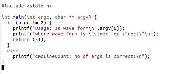
Slide 11: Check the number of cmd line args
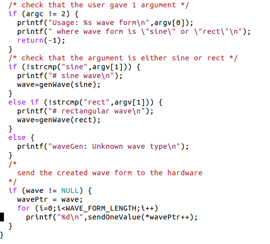
Write a piece of code that checks that the user has entered 1 arguments The program prints a Usage message and exits if the no of arguments given by the user is not exactly 1Slide 12: Solution: arg count

Slide 13: Argument Check
If the no of args is correct we have to check if the argument given is either- sine
- or rect
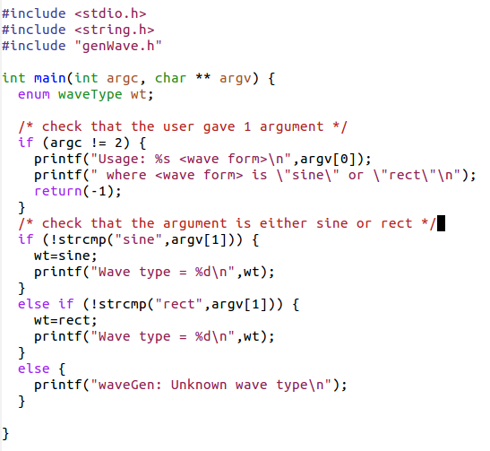
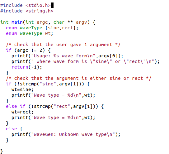
Slide 14: Check the argument
Improve your program to include a check if the argument given is sine or rect. Print an error message it it is not and a success message if it is.Slide 15: Solution: argument check

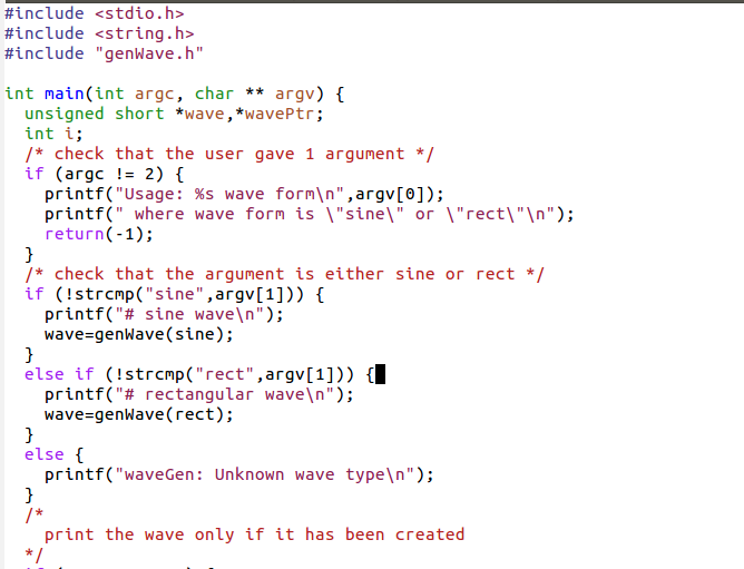
Slide 16: Creating the wave form
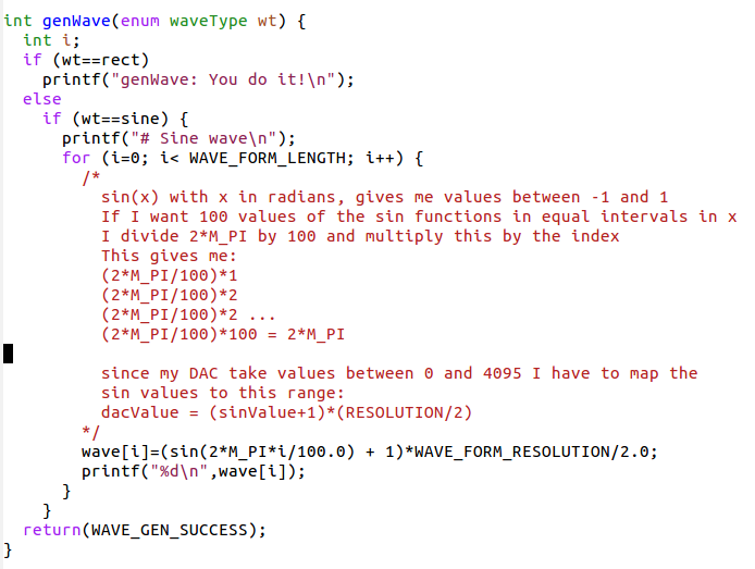
As we said, the DAC takes 12 bit values which can be stored in an array of short (16 bits) The upper 4 bits of each element will be zero The generation of the waveform goes into a separate source file and its associated include file I give you the example for the sine wave and you write the code for the rectangular waveSlide 17: Function test
First we create the framework We will need:- the function itself (genWave.c)
- an include file describing it (genWave.h) and containing
definitions needed by it and useful to the calling program - a main routine (createWaveForm.c) to call it
Slide 18: Write the Test function
Write a test function (genWaveTest.c) taking one argument (the wave type) and printing which wave type has been selected. Which definitions should go into the include file? How do you have to modify the main program to call the genWave function?Slide 19: Dummy function and test (main)

Slide 20: The include file

Slide 21: The test function

Slide 22: Implementing the function

Slide 23: Was it correct?

Slide 24: The rectangular wave form
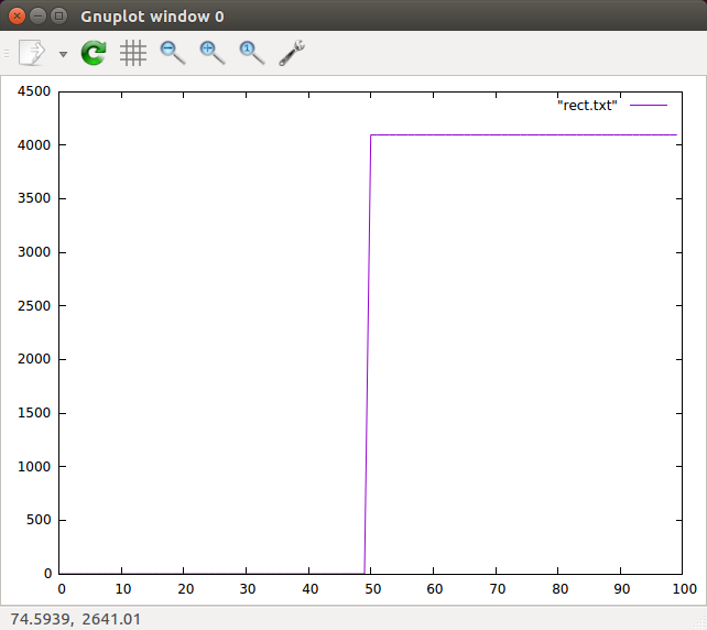
Write the code for the generation of the rectangular wave form. The signal should be zero for the first 50 values of the wave, 4095 for the following 50 valuesSlide 25: Solution: Rectangular wave

Slide 26: The rectangular wave form

Slide 27: Bit handling functions
We need to learn a few bit handling operators before being able to prepare the data for the DAC: | : bitwise or & : bitwise and data += 5 <=> data = data + 5 data |= 5 <=> data = data | 5 ~data: invert all bits in data data >> 4 all bits in data are shifted right by 4 data << 4 all bits in data are shifted left by 4 example:data = 16 00010000 data >> 4 00000001
Slide 28: DAC preparation
Write a function which prepares a byte for the DAC The functions takes 3 arguments:- The data nibble (4 bits of data)
- The register selection (0,1,2)
- The read/write bit
- Leave the strobe bit zero!
Slide 29: Solution: DAC preparation

Slide 30: Now the test program

Slide 31: Strobe
Now create a strobe function which takes DAC data and generates a strobe signal on the STR line without touching the other bitsSlide 32: Solution: Strobe

Slide 33: Send one short value to the DAC
Now that we know how to strobe, it is easy to write a 12 bit value to the DAC We must do it in 3 steps:- "and" out all the bits in the data word
except the last 4 (first data nibble) - or in the rw and register bits (must be reg 0! )
and send the dataByte to strobe
- Shift the data word by for bits and do the same thing
(now the register bits must be 1 of course)
- Shift again by 4 bits and repeat
Slide 34: Solution: send one data word
 4
4
Slide 35: ...and the test program for it

Slide 36: with the result

Slide 37: Assembling the whole thing
Now we have all the bits and pieces and finalizing the project becomes easy. In the file accessing the hardware we add: and we call this in main.
Slide 38: And this is the final result
 --
-- Comments


| I | Attachment | History | Action | Size | Date | Who | Comment |
|---|---|---|---|---|---|---|---|
| |
argCheckv2.png | r1 | manage | 48.4 K | 2017-11-03 - 14:46 | UnknownUser | |
| |
checkArgs.png | r1 | manage | 48.6 K | 2017-10-09 - 08:31 | UnknownUser | |
| |
cmdLineCount.png | r1 | manage | 20.8 K | 2017-10-09 - 08:31 | UnknownUser | |
| |
cmdLineCountv2.png | r1 | manage | 21.0 K | 2017-11-03 - 14:44 | UnknownUser | |
| |
createWaveForm.png | r1 | manage | 63.2 K | 2017-10-09 - 08:31 | UnknownUser | |
| |
dacPrep.png | r1 | manage | 42.0 K | 2017-10-09 - 08:31 | UnknownUser | |
| |
dacPrepResult.png | r1 | manage | 8.7 K | 2017-10-09 - 08:31 | UnknownUser | |
| |
functionTest.png | r1 | manage | 40.2 K | 2017-10-09 - 08:31 | UnknownUser | |
| |
genWaveTest.png | r1 | manage | 24.4 K | 2017-10-09 - 08:31 | UnknownUser | |
| |
genWavev2.png | r1 | manage | 58.1 K | 2017-11-03 - 14:53 | UnknownUser | |
| |
gnuplot.png | r1 | manage | 36.2 K | 2017-10-09 - 08:31 | UnknownUser | |
| |
gnuplotRect.png | r1 | manage | 29.1 K | 2017-10-09 - 08:32 | UnknownUser | |
| |
includeFile.png | r1 | manage | 35.4 K | 2017-10-09 - 08:32 | UnknownUser | |
| |
pulseGenResult.png | r1 | manage | 36.0 K | 2017-10-09 - 08:32 | UnknownUser | |
| |
rectWave.png | r1 | manage | 29.0 K | 2017-10-09 - 08:32 | UnknownUser | |
| |
rectWaveGnuPlot.png | r1 | manage | 29.2 K | 2017-10-09 - 08:32 | UnknownUser | |
| |
scope.png | r1 | manage | 81.0 K | 2017-10-09 - 08:32 | UnknownUser | |
| |
sendOneValue.png | r1 | manage | 32.4 K | 2017-10-09 - 08:32 | UnknownUser | |
| |
sendToDAC.png | r1 | manage | 29.7 K | 2017-10-09 - 08:32 | UnknownUser | |
| |
sendToHWInclude.png | r1 | manage | 28.4 K | 2017-10-09 - 08:32 | UnknownUser | |
| |
sendToHWTest.png | r1 | manage | 48.3 K | 2017-10-09 - 08:32 | UnknownUser | |
| |
sendToHWTestResult.png | r1 | manage | 29.5 K | 2017-10-09 - 08:32 | UnknownUser | |
| |
sendWave.png | r1 | manage | 52.1 K | 2017-10-09 - 08:32 | UnknownUser | |
| |
sine.png | r1 | manage | 71.0 K | 2017-10-09 - 08:32 | UnknownUser | |
| |
sineFunc.png | r1 | manage | 67.0 K | 2017-10-09 - 08:32 | UnknownUser | |
| |
strobe.png | r1 | manage | 45.1 K | 2017-10-09 - 08:32 | UnknownUser | |
| |
waveGen.odp | r1 | manage | 767.6 K | 2017-10-16 - 12:39 | UnknownUser | |
| |
waveGen.tar.gz | r1 | manage | 813.9 K | 2017-10-09 - 08:31 | UnknownUser |

Ideas, requests, problems regarding TWiki? Send feedback